The Sipwise C5 CARRIER platform is composed by a cluster of four different node types, which are all deployed in active/standby pairs:
- Web-Servers (web1a/web1b): Provide northbound interfaces (CSC, API) via HTTPS for provisioning
- DB-Servers (db1a/db1b): Provide the central persistent SQL data store for customer data, peering configuration, billing data etc.
- Proxy-Servers (proxy1a/proxy1b .. proxy4a/proxy4b): Provide the SIP and XMPP signalling engines, application servers and media relays to route Calls and IM/Presence and serve media to the endpoints.
- Load-Balancers (lb1a/lb1b): Provide a perimeter for SIP and XMPP signalling.
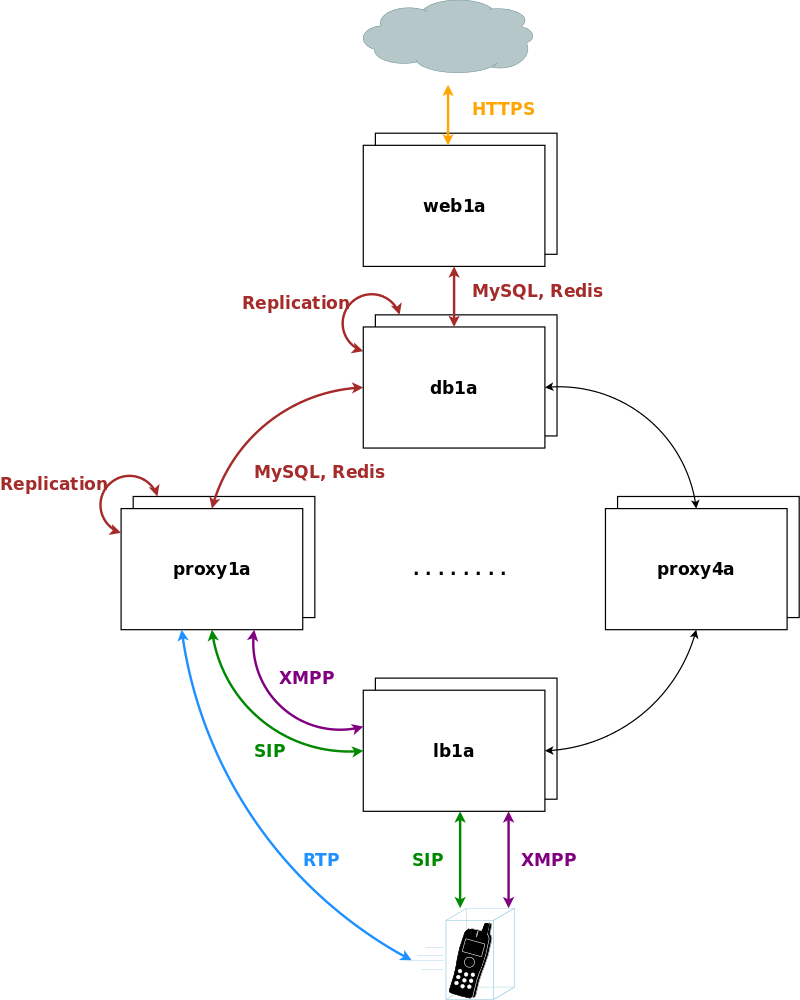
The system is provisioned via the web servers on a central pair of db servers. Signalling is entering the system via the lb servers to a cluster of proxies, which in turn communicate directly (caching and shared data) and indirectly (static provisioning data replicated via master/slave) with the db servers. Each pair of proxy is capable of handling any subscriber, so subscribers are not bound to specific "home proxies". Once a call starts on a proxy pair, it is ensured that the full range of services is provided on that pair (voicemail, media, billing, …) until call-teardown. Failures on an active proxy node cause a fail-over to the corresponding stand-by node within the proxy pair, taking over the full signalling and media without interruptions.
The Sipwise C5 PRO platform consists of two identical appliances working in active/standby mode. The components of a node are outlined in the following figure:
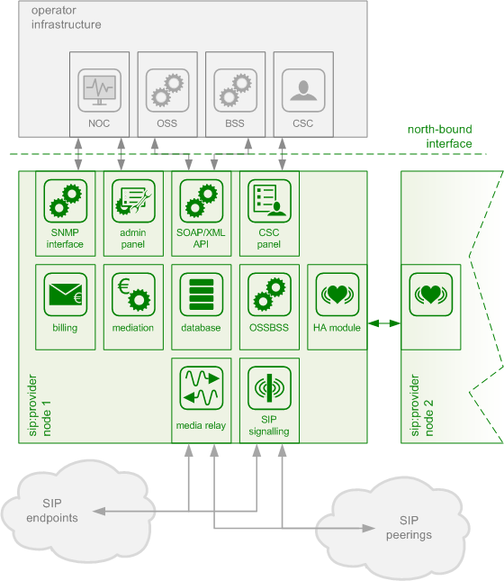
The main building blocks of Sipwise C5 are:
- Provisioning
- SIP Signaling and Media Relay
- Mediation and Billing
- Monitoring and Alerting
- High Availability and Fail-Over
Any HTTPS traffic for provisioning (web interfaces, northbound APIs) but also for phone auto-provisioning enters the platform on the active web server. The web server runs an nginx instance acting as a reverse proxy for the ngcp-panel process, which in turn provides the provisioning functionality.
The web server is connected to the db server pair, which provides a persistent relational data store via MySQL and a high-performance system cache using Redis key-value store.
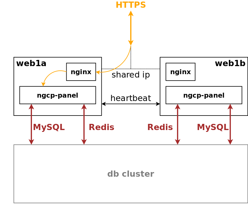
The web server pair is an active/standby pair of nodes connected via an HA service (GCS/CRM). If one of the servers fail (by losing connection to the outside while the standby server is still connected, or caused by a hardware failure, or if it’s down due to maintenance), the standby server takes over the shared IP address of the active node and continues serving the provisioning interface.
In SIP-based communication networks, it is important to understand that the signaling path (e.g. for call setup and tear-down) is completely independent of the media path. On the signaling path, the involved endpoints negotiate the call routing (which user calls which endpoint, and via which path - e.g. using SIP peerings or going through the PSTN - the call is established) as well as the media attributes (via which IPs/ports are media streams sent and which capabilities do these streams have - e.g. video using H.261 or Fax using T.38 or plain voice using G.711). Once the negotiation on signaling level is done, the endpoints start to send their media streams via the negotiated paths.
On a CARRIER any signalling traffic enters and leaves the system via load balancers, which act as a perimeter towards the customer devices and performs NAT handling, DoS and DDoS mitigation. New connections are routed to a random pair of proxy servers, which do the actual routing for SIP and XMPP. The proxy servers also engage media relays for voice and video streams, which bypass the load balancers and communicate directly with the customer devices for performance reasons.
The components involved in SIP and Media on the Sipwise C5 PRO/CARRIER are shown in the following figure:
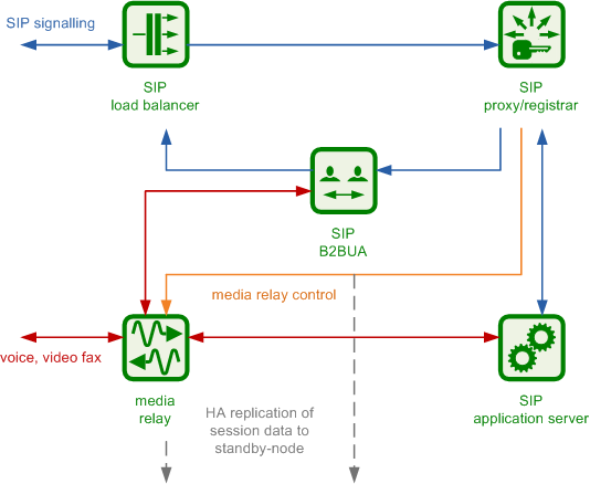
The SIP load-balancer is a Kamailio instance acting as ingress and egress point for all SIP traffic to and from the system. It’s a high-performance SIP proxy instance based on Kamailio and is responsible for sanity checks of inbound SIP traffic. It filters broken SIP messages, rejects loops and relay attempts and detects denial-of-service and brute-force attacks and gracefully handles them to protect the underlying SIP elements. It also performs the conversion of TLS to internal UDP and vice versa for secure signaling between endpoints and Sipwise C5, and does far-end NAT traversal in order to enable signaling through NAT devices.
The load-balancer is the only SIP element in the system which exposes a SIP interface to the public network. Its second leg binds in the switch-internal network to pass traffic from the public internet to the corresponding internal components.
The name load-balancer comes from the fact that when scaling out Sipwise C5 beyond just one pair of servers, the load-balancer instance becomes its own physical node and then handles multiple pairs of proxies behind it.
On the public interface, the load-balancer listens on port 5060 for UDP and TCP, as well as on 5061 for TLS connections. On the internal interface, it speaks SIP via UDP on port 5060 to the other system components, and listens for XMLRPC connections on TCP port 5060, which can be used to control the daemon.
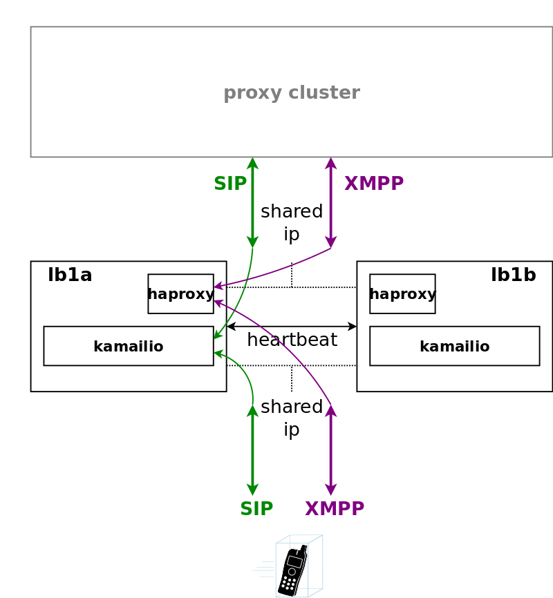
A node in a load balancer pair runs two services besides the usual HA service.
One is a state-less instance of kamailio, providing an extremely fast relay of SIP messages. Kamailio takes care of converting TCP and TLS connections from the customer devices to UDP for internal communication towards proxies, and it performs far-end NAT traversal by inspecting the SIP messages and comparing it to the actual source address where packets have been received from, then modifying the SIP messages accordingly. If a SIP message is received by the load balancer, it distinguishes between new and ongoing SIP transactions by inspecting the To-Tags of a message, and it determines whether the message is part of an established dialog by inspecting the Route header. Sanity checks are performed on the headers to make sure the call flows adhere to certain rules for not being able to bypass any required element in the routing path. In-dialog messages are routed to the corresponding proxy servers according to the Route defined in the message. Messages initiating a new transaction and/or dialog (registrations, calls etc) are routed to a randomly selected proxy. The selection algorithm is based on a hash over the Call-ID of the message, so the same proxy sending a authentication challenge to an endpoint will receive the authenticated message again.
The second service running on a load balancer is haproxy, which is acting as load balancing instance for XMPP messages. The same way the SIP load balancer routes SIP messages to the corresponding proxy, the haproxy passes XMPP traffic on to the proxy maintaining a session with a subscriber, or randomly selects a proxy in case of a new connection while automatically failing over on timeouts.
Its config files reside in /etc/ngcp-config/templates/etc/kamailio/lb/,
and changes to these files are applied by executing
ngcpcfg apply "my commit message".
| tip | |
The SIP load-balancer can be managed via the commands
|
The SIP proxy/registrar (or short proxy) is the work-horse of Sipwise C5. It’s also a separate Kamailio instance running in the switch-internal network and is connected to the provisioning database via MySQL, authenticates the endpoints, handles their registrations on the system and does the call routing based on the provisioning data. For each call, the proxy looks up the provisioned features of both the calling and the called party (either subscriber or domain features if it’s a local caller and/or callee, or peering features if it’s from/to an external endpoint) and acts accordingly, e.g. by checking if the call is blocked, by placing call-forwards if applicable and by normalizing numbers into the appropriate format, depending on the source and destination of a call.
It also writes start- and stop-records for each call, which are then transformed into call detail records (CDR) by the mediation system.
If the endpoints indicate negotiation of one or more media streams, the proxy also interacts with the Media Relay to open, change and close port pairs for relaying media streams over Sipwise C5, which is especially important to traverse NAT.
The proxy listens on UDP port 5062 in the system-internal network. It cannot be reached directly from the outside, but only via the SIP load-balancer.
Its config files reside in /etc/ngcp-config/templates/etc/kamailio/proxy/, and changes to these files are applied by executing ngcpcfg apply "my commit message".
| tip | |
The SIP proxy can be controlled via the commands
|
The SIP B2BUA (also called SBC within the system) decouples the first call-leg (calling party to Sipwise C5) from the second call-leg (Sipwise C5 to the called party).
The software part used for this element is a commercial version of SEMS, with the main difference to the open-source version that it includes a replication module to share its call states with the stand-by node.
This element is typically optional in SIP systems, but it is always used for SIP calls (INVITE) that don’t have Sipwise C5 as endpoint. It acts as application server for various scenarios (e.g. for feature provisioning via Vertical Service Codes and as Conferencing Server) and performs the B2BUA decoupling, topology hiding, caller information hiding, SIP header and Media feature filtering, outbound registration, outbound authentication, Prepaid accounting and call length limitation as well as Session Keep-Alive handler.
Due to the fact that typical SIP proxies (like the load-balancer and proxy in Sipwise C5) do only interfere with the content of SIP messages where it’s necessary for the SIP routing, but otherwise leave the message intact as received from the endpoints, whereas the B2BUA creates a new call leg with a new SIP message from scratch towards the called party, SIP message sizes are reduced significantly by the B2BUA. This helps to bring the message size under 1500 bytes (which is a typical default value for the MTU size) when it leaves Sipwise C5. That way, chances of packet fragmentation are quite low, which reduces the risk of running into issues with low-cost SOHO routers at customer sides, which typically have problems with UDP packet fragmentation.
The SIP B2BUA only binds to the system-internal network and listens on UDP port 5080 for SIP messages from the load-balancer or the proxy, on UDP port 5040 for control messages from the cli tool and on TCP port 8090 for XMLRPC connections to control the daemon.
Its configuration files reside in /etc/ngcp-config/templates/etc/ngcp-sems, and changes to these files are applied by executing ngcpcfg apply "my commit message".
| tip | |
The SIP B2BUA can be controlled via the commands
|
The SIP App-Server is an Asterisk instance used for voice applications like Voicemail and Reminder Calls. It is also used in the software-based Faxserver solution to transcode SIP and RTP into the IAX protocol and vice versa, in order to talk to the Software Fax Modems. Asterisk uses the MySQL database as a message spool for voicemail, so it doesn’t directly access the file system for user data. The voicemail plugin is a slightly patched version based on Asterisk 1.4 to make Asterisk aware of Sipwise C5 internal UUIDs for each subscriber. That way a SIP subscriber can have multiple E164 phone numbers, but all of them terminate in the same voicebox.
The App-Server listens on the internal interface on UDP port 5070 for SIP messages and by default uses media ports in the range from UDP port 10000 to 20000.
The configuration files reside in /etc/ngcp-config/templates/etc/asterisk, and changes to these files are applied by executing ngcpcfg apply "my commit message".
| tip | |
The SIP App-Server can be controlled via the commands
|
The Media Relay (also called rtpengine) is a Kernel-based packet relay, which is controlled by the SIP proxy. For each media stream (e.g. a voice and/or video stream), it maintains a pair of ports in the range of port number 30000 to 40000. When the media streams are negotiated, rtpengine opens the ports in user-space and starts relaying the packets to the addresses announced by the endpoints. If packets arrive from different source addresses than announced in the SDP body of the SIP message (e.g. in case of NAT), the source address is implicitly changed to the address the packets are received from. Once the call is established and the rtpengine has received media packets from both endpoints for this call, the media stream is pushed into the kernel and is then handled by a custom Sipwise iptables module to increase the throughput of the system and to reduce the latency of media packets.
The rtpengine internally listens on UDP port 12222 for control messages from the SIP proxy. For each media stream, it opens two pairs of UDP ports on the public interface in the range of 30000 and 40000 per default, one pair on even port numbers for the media data, and one pair on the next odd port numbers for metadata, e.g. RTCP in case of RTP streams. Each endpoint communicates with one dedicated port per media stream (opposed to some implementations which use one pair for both endpoints) to avoid issues in determining where to send a packet to. The rtpengine also sets the QoS/ToS/DSCP field of each IP packet it sends to a configured value, 184 (0xB8, expedited forwarding) by default.
The kernel-internal part of the rtpengine is facilitated through an
iptables module having the target name RTPENGINE. If any
additional firewall or packet filtering rules are installed, it is
imperative that this rule remains untouched and stays in place. Otherwise,
if the rule is removed from iptables, the kernel will not be able to
forward the media packets and forwarding will fall back to the user-space
daemon. The packets will still be forwarded normally, but performance
will be much worse under those circumstances, which will be especially
noticeable when a lot of media streams are active concurrently. See the
section on Firewalling for more information.
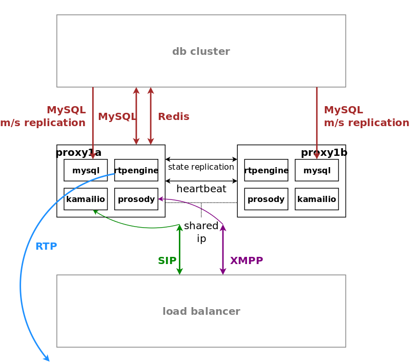
Proxy servers also come in pairs, and by default there are four pairs of proxies in a standard Sipwise C5 CARRIER setup.
The proxies are responsible for doing the actual SIP routing and media handling and the XMPP presence and chat message deliveries. Each proxy pair can handle any subscriber on the overall system, compared to the concept of "home proxies" in other architectures. The advantage of this approach is that the overall system can be scaled extremely easily by adding more proxy pairs without having to redistribute subscribers.
Once a load balancer sends a new message to a proxy, the SIP transaction and/or dialog gets anchored to this proxy. That way it is ensured that a call starting on a proxy is also ended on the same proxy. Hence, the full range of feature handling like media relay, voicemail, fax, billing and rating is performed on this proxy. So, there is no a central point for various tasks, potentially leading to a non-scalable bottleneck. Due to the anchoring, proxies come in pairs and replicate all internal state information to the standby node via redis. In case of fail-over, the full signalling and media are moved to the standby node without interruption.
The complete static subscriber information like authentication credentials, number mappings, feature settings etc. are replicated from the db cluster down to the local MySQL instance of the proxies. The ratio of db read requests of static subscriber data versus reading and writing volatile and shared data is around 15:1, and this approach moves the majority of the static read operations from the central db cluster to the local proxy db.
Volatile and shared information needed by all proxies in the cluster is read from and written to the db cluster. This mainly includes SIP registration information and XMPP connection information.
Billing and rating is also performed locally on the proxies, and only completed CDRs (rated or unrated depending on whether rating is enabled) are transferred to the central db cluster for consumption via the northbound interfaces.
For SIP, the relevant instances on a proxy are kamailio acting as a stateful proxy for SIP registration and call routing, sems acting as a back-to-back user-agent for prepaid billing and application server, rtpengine as media relay and RTP/SRTP transcoder, and asterisk as voicemail server. XMPP is handled by an instance of prosody, and several billing processes mediate start and stop records into CDRs and rate them according to the relevant billing profiles.
The rtpengine configuration file is
/etc/ngcp-config/templates/etc/default/ngcp-rtpengine-daemon, and
changes to this file are applied by executing
ngcpcfg apply "my commit message". The UDP port range can be
configured via the config.yml file under the section rtpproxy.
The QoS/ToS value can be changed via the key qos.tos_rtp.
| tip | |
The Media Relay can be controlled via the commands
|
The MySQL database consists of a pair of active/standby MySQL servers. They run a MySQL master/master replication with replication integrity checks to ensure data consistency and redundancy.
The MySQL servers on both physical nodes synchronize via the row-based master/master replication. In theory, any of the two servers in the pair can be used to write data to the database, however, in practice the shared IP address is used towards clients accessing the service, hence only the active MySQL server will receive the write requests and replicate them to the standby one.
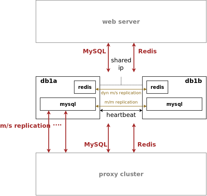
The db server pair is another active/standby pair with automatic fail-over. Nodes in the pair are running a MySQL master/master replication with replication integrity checks to ensure data redundancy and safety. Any changes via provisioning interfaces are stored in the MySQL cluster. The second service is a redis master/slave replication with automatic master propagation on fail-over. This redis cluster is used as a high-performance volatile system cache for various components which need to share state information across nodes.
The MySQL instances on the db nodes synchronize via row-based master/master replication. In theory, any of the two servers in the pair can be used to write data to the database, however in practice a shared IP is used towards clients accessing the service, so only one node will receive the write requests. This is done to ensure transparent and instant convergence of the db cluster on fail-over for the clients.
On top of that, the first node of the db pair also acts as a master in a master/slave replication towards all proxy nodes in the system. That way, proxies can access read-only provisioning data directly from their local databases, resulting in reduced latency and significant off-loading of read queries on the central db cluster.
The redis database is used as a high-perfomance key/value storage for global system datashared across proxies. This includes calls information and concurrent calls counters for customers and subscribers, etc..
The active-standby replication ensures that the data is immediately copied from the active node to the standby one. As all sensitive call information is held in the shared storage, Sipwise C5 makes it possible to switch the operational state from active to standby on one physical node and from standby to active on the other node without any call interruptions. Your subscribers will never notice that their calls being established on one physical server, were successfully moved to another one and successfully completed there.
On a CARRIER a redis master/slave setup is used to provide a high-perfomance key/value storage for global system data shared across proxies. This includes concurrent call counters for customers and subscribers, as a subscriber could place two simultaneous calls via two different proxy pairs.
The two servers of a complete Sipwise C5 system form a pair, a simple cluster with two nodes. Their names are fixed as sp1 and sp2, however neither of them is inherently a first or a second. They’re both equal and identical and either can be the active node of the cluster at any time. Only one node is always ever active, the other one is in standby mode and doesn’t perform any active functions.
High availability is achieved through constant communication between the two nodes and constant state replication from the active node to the standby one. Whenever the standby node detects that the other node has become unresponsive, has gone offline and has failed in any other way, it will proceed with taking over all resources and becoming the active node, with all operations resuming where the failed node has left off. Through that, the system will remain fully operational and service disruption will be minimal.
When the failed node comes back to life, it will become the new standby node, replicate everything that has changed in the meantime from the new active node, and then the cluster will be back in fully highly available state.
| tip | |
The login banner at the SSH shell provides information about whether the local system is currently the active one or the standby one. See Section 2.7.4, “Administration” for other ways to differentiate between the active and the standby node. |
The HA architecture consists of two components: the Group Communication System, also known as GCS, and the Cluster Resource Manager, also known as CRM. Sipwise C5 supports two alternatives for these components:
- Heartbeat version 2: This is the older and more basic software which provides both GCS and CRM services. It’s still the default for Sipwise C5 installations but will be obsoleted in a future release.
- Corosync/Pacemaker: This is the newer and more modern software and the successor of Heartbeat version 2. It splits the HA framework into its two components, with Corosync providing the GCS service and Pacemaker providing the CRM service. It provides several additional features over Heartbeat version 2 and will be made the default choice in a future release.
| caution | |
Because migration from a Heartbeat version 2 installation to a
Corosync/Pacemaker installation requires installation and removal of certain
software packages, a script |
The direct Ethernet crosslink between the two nodes provides the main mechanism of HA communication between them. All state replication happens over this link. Additionally, the GCS service uses this link to communicate with the other node to see if it’s still alive and active. A break in this link will therefore result in a split brain scenario, with either node trying to become the active one. This is to be avoided at all costs.
The config.yml file allows specification of a list of ping nodes under
the key heartbeat.pingnodes, which are used by the CRM service to determine
if local network communications are healthy. Both servers will then constantly
compare the number of locally reachable ping nodes with each other, and if the
standby server is able to reach more of them, then it will become the active
one.
The main resource that the CRM service manages is the shared service IP address.
Each node has its own static IP address configured on its first Ethernet
interface (eth0), which is done outside of the Sipwise C5 configuration
framework (i.e. in the Debian-specific config file /etc/network/interfaces).
The shared service IP is specified in network.yml at the key
hosts.sp1|sp2.eth0.shared_ip. The CRM service will configure it as a
secondary IP address on the first Ethernet interface (eth0:0) on the active
node and will deconfigure it on the standby node. Thus, all network
communications with this IP address will always go only to the currently active
node.
The current status of the local Sipwise C5 node can be determined using
the ngcp-check-active shell command. This command produces no output,
but returns an exit status of 0 for the active node and 1 for the
standby node. A more complete shell command to produce visible output could
be: ngcp-check-active -v
To force a currently active node into standby mode, use the command
ngcp-make-standby. For the opposite effect, use the command
ngcp-make-active. This will also always affect the state of the other
node, as the system automatically makes sure that always only one node is
active at a time.