This chapter will describe the hardware requirements of the Sipwise C5 platforms. And will provide the step by step instructions on how to put a PRO system into operation. There are currently no published instructions on how to put a CARRIER system into operation.
Sipwise C5 CARRIER starts with a minimum deployment of 50.000 subscribers, requiring one chassis with two web servers, two db servers, two load balancers and two proxies. A fully deployed Sipwise C5 CARRIER for 200.000 subscribers fills the chassis up with 14 servers, containing two web servers, two db servers, two load balancers and 8 proxies.
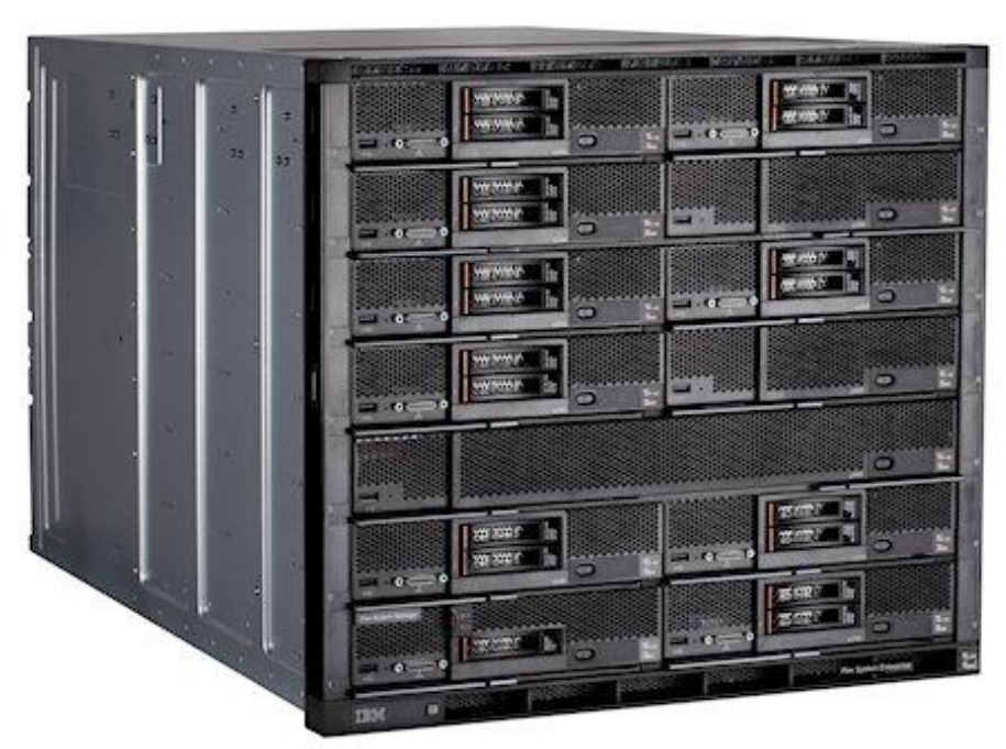
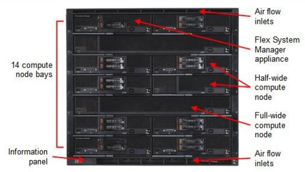
The system is based on an IBM Flex Chassis taking up rack space of 10U with 14 computing nodes based on IBM x240 servers.
All nodes are equipped equally with two hard disks in Raid-1 mode.
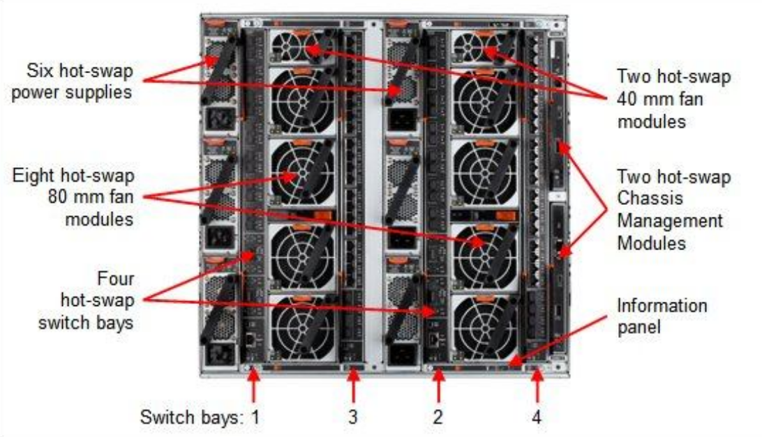
The power supply is designed fully redundant in an N+N fashion with N=3, for example to feed 3 PSUs with normal power and 3 PSUs with UPS power.
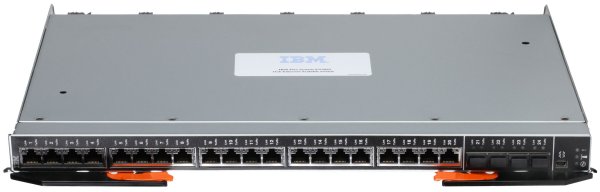
Each chassis is equipped with two EN2092 Gigabit Ethernet switches providing 10 1GbE uplinks each. Four 10GbE uplinks are optional and need to be licensed separately if needed.
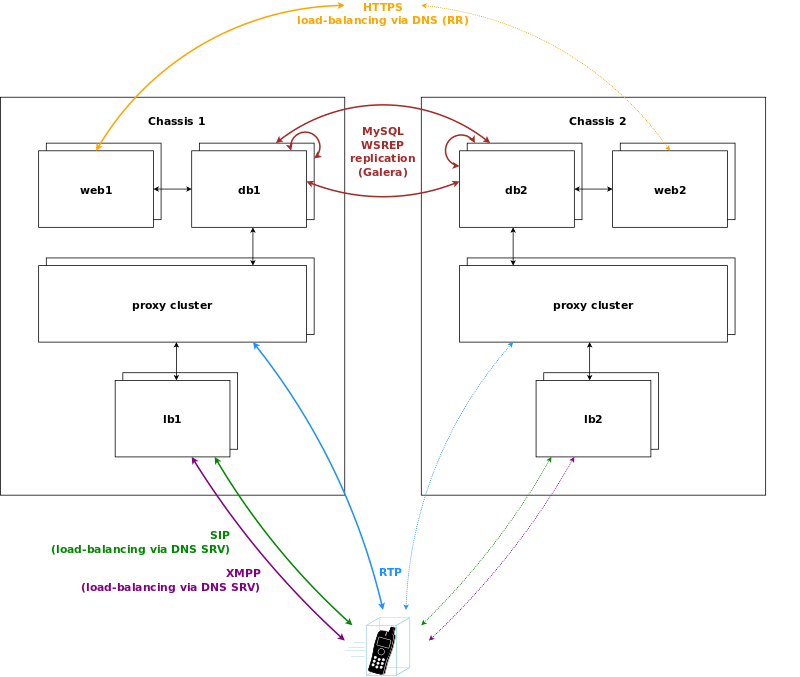
If Sipwise C5 CARRIER is scaled beyond 250.000 subscribers and therefore exceeds one chassis, a second chassis is put into place. This chassis provides another two web servers, two db servers, two load balancers and 8 proxies, doubling the capacity of the system.
The DB cluster is the only node type which requires a notable change on the architecture. Once more than one db pair is deployed, the replication mechanism between db nodes changes from master/master between the nodes of the db1 pair to a synchronous multi-master replication over all db nodes on the system using Galera. This change makes it possible to scale both read and write requests over multiple nodes, while being transparent to all other nodes.
New proxy nodes replicate via master/slave from the first db node in the chassis as usual. Since the db cluster holds all provisioning information of all subscribers, the proxy nodes join the cluster transparently and will start serving subscribers as soon as all services on a new proxy are reachable from the load balancers.
Load balancers are completely stateless, so they start serving subscribers as soon as they are made visible to the subscribers. This could either be done via DNS round-robin, but the better approach is to configure a DNS SRV record, which allows for more fine-grained control like weighting load-balancer pairs and allowing fail-over from one pair to another on the client side.
The load balancers use the Path extension of SIP to make sure during SIP registration that calls targeted to a subscriber are routed via the same load balancer pair which the subscriber used during registration for proper traversal of symmetric NAT at the customer premise.
A SIP or XMPP request reaching a load balancer can be routed to any available proxy in the whole system, or only to proxies belonging to the same chassis as the load balancer, depending on the system configuration.
| tip | |
This architecture is not part of the standard deployment and is to be defined in the project plan! |
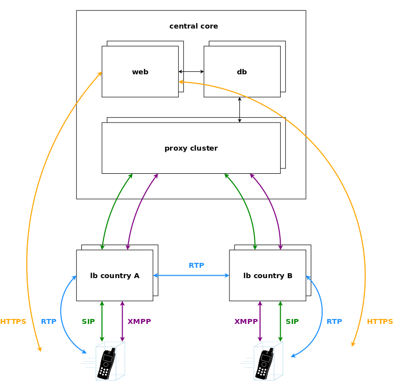
In case of a geographically distributed system spanning across multiple countries, different regulatory requirements have to be met for signalling and media, especially when it comes to if, where and how subscriber traffic can be intercepted. Countries might have the requirement to intercept traffic in the country, so the signalling and media must be anchored to an element in the country. Also if a media stream stays within a country, it is preferred to keep the media as close to the subscribers as possible to reduce latency, so relaying streams via a central core has to be avoided.
For this scenario, Sipwise C5 CARRIER makes it possible to move the load balancers directly into the countries. DNS settings for subscribers within the country ensure that they will always contact those load balancers, either using separate DNS settings per country for a SIP domain, or using GeoIP mechanisms in DNS to return the closest load balancer based on the location of the subscriber. To anchor media to the countries, the rtpengine instances are moved from the proxies to the load balancers and are controlled via the stateless kamailio instances on the load balancers instead of the kamailio instances on the proxies.
Sipwise provides Sipwise C5 platform fully pre-installed on two Dell PowerEdge R330 servers. Their most important characteristics are:
- Up to 8 pcs. of 2.5" storage drives (HDD or SSD); shipped with 4 drives installed and configured as RAID10 array
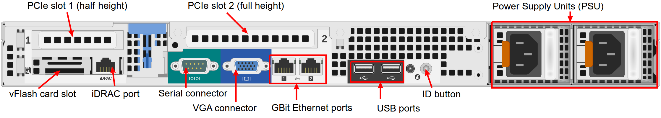
- Gbit Ethernet ports: 2 on-board and 2 additional ports (optional)
- iDRAC module for remote maintenance
| info | |
Please be aware that prior to Q3 2016 Sipwise used to provide its Sipwise C5 platform on older Dell PowerEdge server models: R310 and R320. |
The hardware dimensions are defined in the following figure:
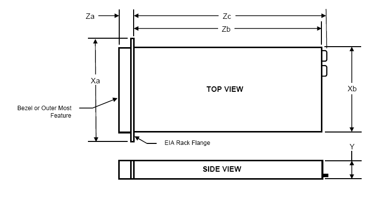
Xa | Xb (Width) | Y (Height) | Za w/ bezel | Za w/o bezel | Zb (Depth) | Zc |
482.4mm | 434mm | 42.8mm | 35mm | 21mm | 610mm | 639.5mm |
Weight of the server with storage drives and internal components installed: 13.4kg
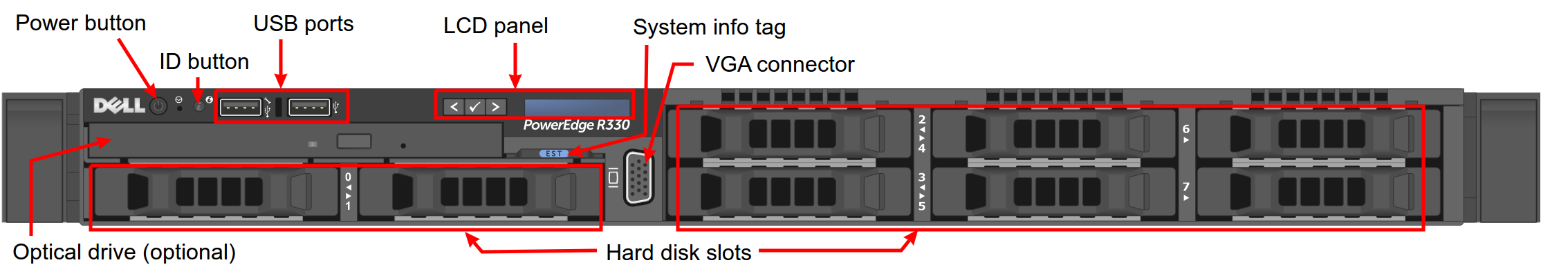
The front view of a current Sipwise C5 Dell R330 server:
The front view of a former Sipwise C5 Dell R310…:
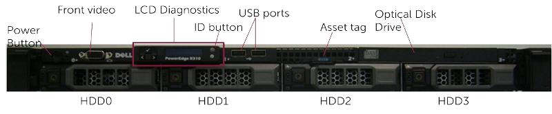
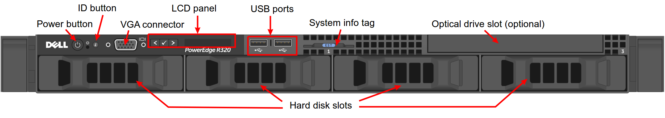
…and Dell R320 server:
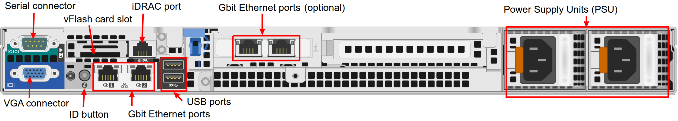
The rear view of a current Sipwise C5 Dell R330 server:
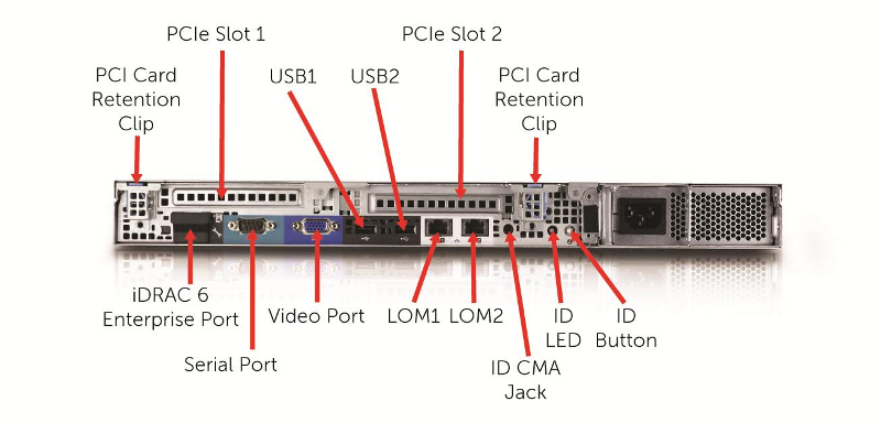
The rear view of a former Sipwise C5 Dell R310…:
…and Dell R320 server:
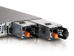
The servers are equipped with 2 redundant, hot-swappable PSUs, which are accessible from the rear side and located on the right of the chassis:
The redundant PSUs include LEDs that indicate the status of the PSU:
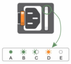
- The indicator is solidly lit green: A valid power source is connected to the PSU and the PSU is operational.
The indicator is flashing green: The PSU firmware is being updated.
caution Do not disconnect the power cord or unplug the PSU when updating the firmware. If a firmware update is interrupted, the PSUs will not function. You must roll back the PSU firmware by using Dell Lifecycle Controller. For more information, see Dell Lifecycle Controller User’s Guide at Dell.com/idracmanuals.
- The indicator is flashing green and turns off: When hot-adding a PSU, the PSU handle flashes green five times at 4 Hz rate and turns off. This indicates that there is a PSU mismatch with respect to efficiency, feature set, health status, and supported voltage. Ensure that both the PSUs are the same.
The indicator is flashing amber: Indicates a problem with the PSU.
caution When correcting a PSU mismatch, replace only the PSU with the flashing indicator. Swapping the other PSU to make a matched pair can result in an error condition and unexpected system shutdown. To change from a High Output configuration to a Low Output configuration or vice versa, you must turn off the system.
caution AC PSUs support both 220 V and 110 V input voltages with the exception of Titanium PSUs, which support only 220 V. When two identical PSUs receive different input voltages, they can output different wattages, and trigger a mismatch.
caution If two PSUs are used, they must be of the same type and have the same maximum output power.
caution Combining AC and DC PSUs is not supported and triggers a mismatch.
- The indicator is not lit: Power is not connected.
In order to put Sipwise C5 into operation, you need to rack-mount it into 19" racks.
You will find the following equipment in the box:
- 2 servers
- 2 pairs of rails to rack-mount the servers
- 2 cable management arms
You will additionally need the following parts as they are not part of the distribution:
4 power cables
info The exact type required depends on the location of installation, e.g. there are various forms of power outlets in different countries.
- At least 2 CAT5 cables to connect the servers to the access switches for external communication
- 1 CAT5 cable to directly connect the two servers for internal communication
Install the two servers into the rack (either into a single one or into two geographically distributed ones).
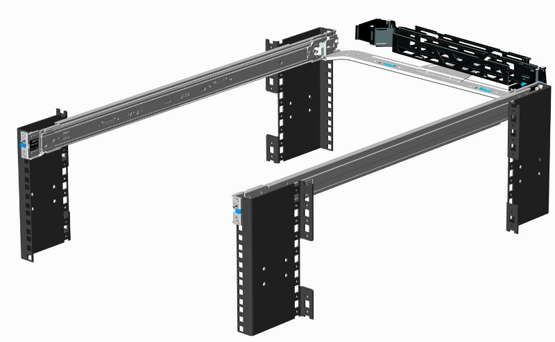
The rails shipped with the servers fit into standard 4-Post 19" racks. If they do not fit, please consult your rack vendor to get proper rails.
The following figure shows the mounted rails:
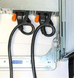
Each server has two redundant Power Supply Units (PSU). Connect one PSU to your normal power circuit and the other one to an Uninterruptible Power Supply Unit (UPS) to gain the maximum protection against power failures.
The cabling should look like in the following picture to prevent accidental power cuts:
- Internal Communication
- The high availability (HA) feature of Sipwise C5 requires that a direct Ethernet connection between the servers is established. One of the network interfaces must be dedicated to this functionality.
- External Communication
- Remaining network interfaces may be used to make the servers publicly available for communication services (SIP, messaging, etc.) and also for their management and maintenance.
Patch a cross-link with a straight CAT5 cable between the two servers by connecting the cable to the network interface assigned to the HA component by Sipwise. The direct cross cable is applied for maximum availability because this connection is used by the servers to communicate with each other internally.
| important | |
We strongly suggest against using a switch in between the servers for this internal interface. Using a switch is acceptable only if there is no another way to connect the two ports (e.g. if you configure a geographically distributed installation). |
| info | |
In case you are using a switch for cross-link make sure to enable portfast
mode on Cisco switches. The thing is that STP puts the port into learning mode for
90 seconds, after it comes up for the first time. During this learning phase, the
link is technically up, but no traffic passes through, so the GCS service will
detect the other node as dead during boot. The portfast mode tells the switch
to skip the learning phase and go to forwarding state right away:
|
For both servers, depending on the network configuration, connect one or more straight CAT5 cables to the ports on the servers network cards and plug them into the corresponding switch ports. Information about proper ports of the servers to be used for this purpose are provided by Sipwise.