| |
| |
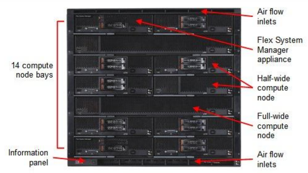
The sip:carrier starts with a minimum deployment of 50.000 subscribers, requiring one chassis with two web servers, two db servers, two load balancers and two proxies. A fully deployed sip:carrier for 250.000 subscribers fills the chassis up with 14 servers, containing two web servers, two db servers, two load balancers and 8 proxies.
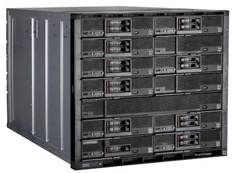
The system is based on an IBM Flex Chassis taking up rack space of 10U with 14 computing nodes based on IBM x220 servers.
All nodes are equipped equally with two hard disks in Raid-1 mode.
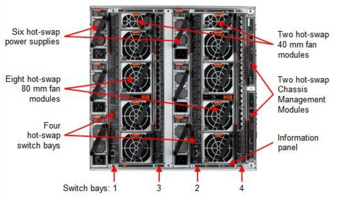
The power supply is designed fully redundant in an N+N fashion with N=3, for example to feed 3 PSUs with normal power and 3 PSUs with UPS power.
Each chassis is equipped with two EN2092 Gigabit Ethernet switches providing 10 GbE uplinks each. Four 10GbE uplinks are optional and need to be licensed separately if needed.
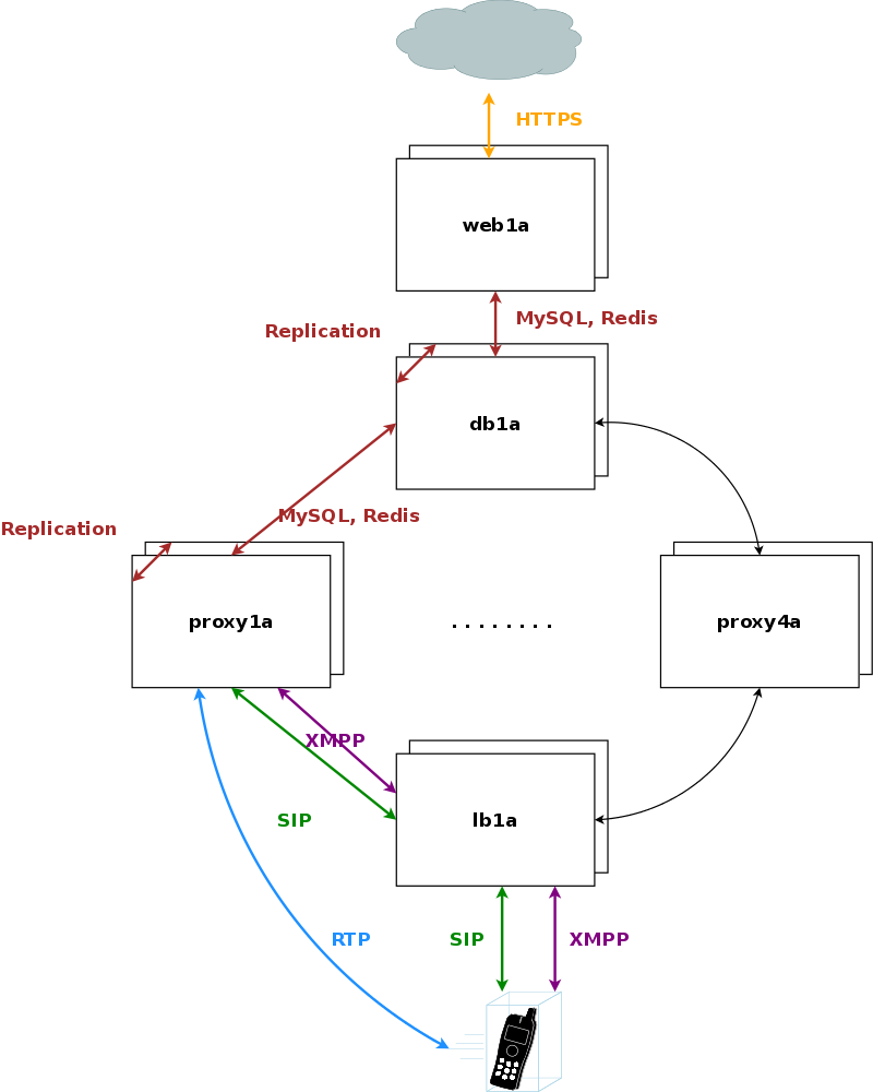
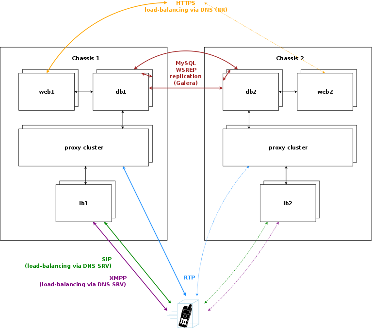
The sip:carrier is composed by a cluster of four different node types, which are all deployed in active/standby pairs:
The system is provisioned via the web servers on a central pair of db servers. Signalling is entering the system via the lb servers to a cluster of proxies, which in turn communicate directly (caching and shared data) and indirectly (static provisioning data replicated via master/slave) with the db servers. Each pair of proxy is capable of handling any subscriber, so subscribers are not bound to specific "home proxies". Once a call starts on a proxy pair, it is ensured that the full range of services is provided on that pair (voicemail, media, billing, …) until call-teardown. Failures on an active proxy node cause a fail-over to the corresponding stand-by node within the proxy pair, taking over the full signalling and media without interruptions.
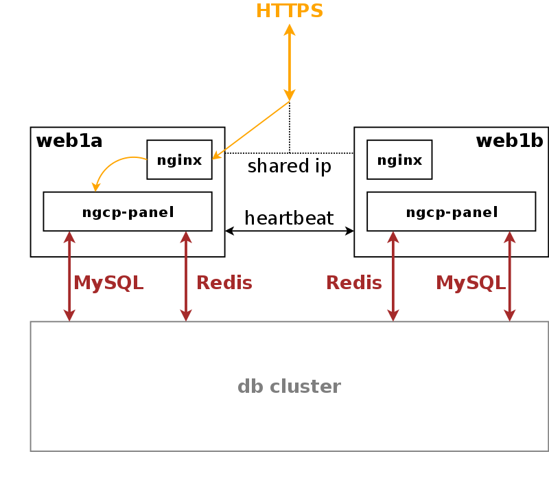
Any HTTPS traffic for provisioning (web interfaces, northbound APIs) but also for phone auto-provisioning enters the platform on the active web server. The web server runs an nginx instance acting as a reverse proxy for the ngcp-panel process, which in turn provides the provisioning functionality.
The web server is connected to the db server pair, which provides a persistent relational data store via MySQL and a high-performance system cache using Redis key-value store.
The web server pair is an active/standby pair of nodes connected via heartbeat. If one of the servers fail (by losing connection to the outside while the standby server is still connected, or caused by a hardware failure, or if it’s down due to maintenance), the standby server takes over the shared IP address of the active node and continues serving the provisioning interface.
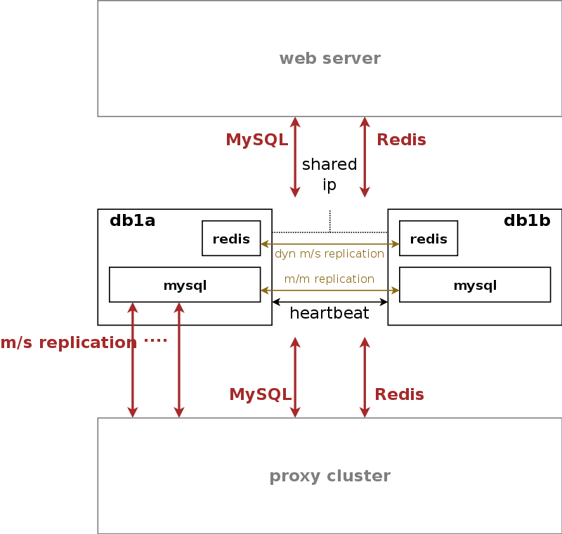
The db server pair is another active/standby pair with automatic fail-over. Nodes in the pair are running a MySQL master/master replication with replication integrity checks to ensure data redundancy and safety. Any changes via provisioning interfaces are stored in the MySQL cluster. The second service is a redis master/slave replication with automatic master propagation on fail-over. This redis cluster is used as a high-performance volatile system cache for various components which need to share state information across nodes.
The MySQL instances on the db nodes synchronize via row-based master/master replication. In theory, any of the two servers in the pair can be used to write data to the database, however in practice a shared IP is used towards clients accessing the service, so only one node will receive the write requests. This is done to ensure transparent and instant convergence of the db cluster on fail-over for the clients.
On top of that, the first node of the db pair also acts as a master in a master/slave replication towards all proxy nodes in the system. That way, proxies can access read-only provisioning data directly from their local databases, resulting in reduced latency and significant off-loading of read queries on the central db cluster.
A redis master/slave setup is used to provide a high-perfomance key/value storage for global system data shared across proxies. This includes concurrent call counters for customers and subscribers, as a subscriber could place two simultaneous calls via two different proxy pairs.
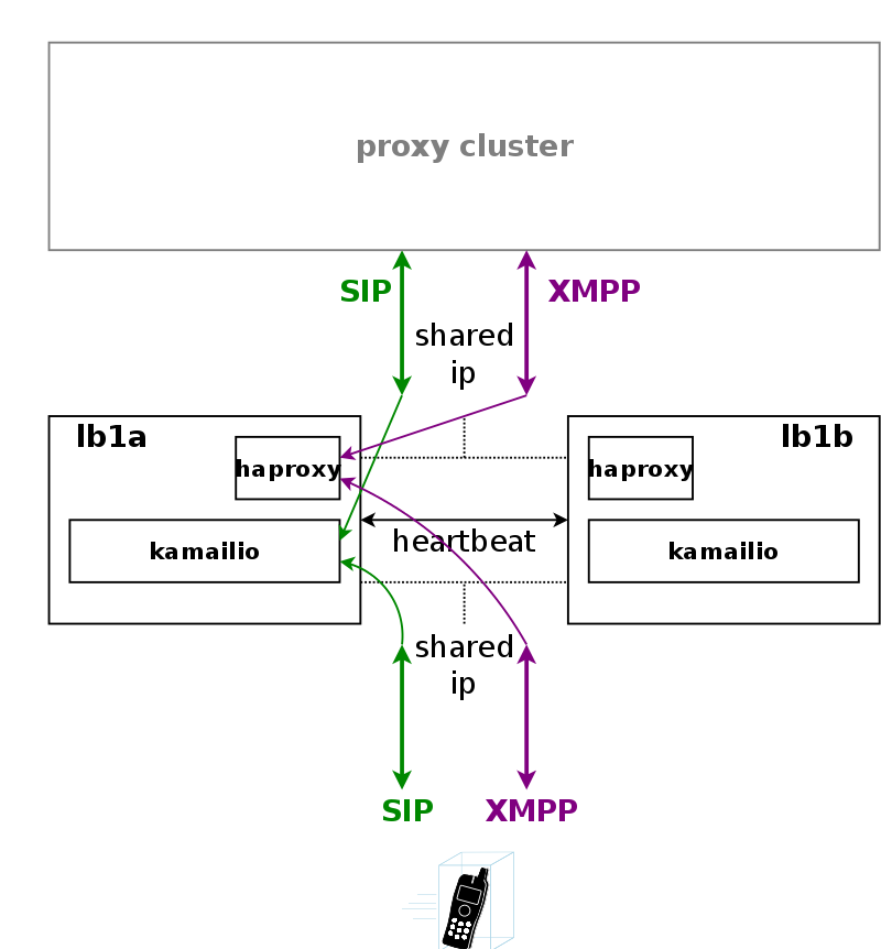
Any signalling traffic enters and leaves the system via load balancers, which act as a perimeter towards the customer devices and performs NAT handling, DoS and DDoS mitigation. New connections are routed to a random pair of proxy servers, which do the actual routing for SIP and XMPP. The proxy servers also engage media relays for voice and video streams, which bypass the load balancers and communicate directly with the customer devices for performance reasons.
A node in a load balancer pair runs two services besides the usual heartbeat.
One is a state-less instance of kamailio, providing an extremely fast relay of SIP messages. Kamailio takes care of converting TCP and TLS connections from the customer devices to UDP for internal communication towards proxies, and it performs far-end NAT traversal by inspecting the SIP messages and comparing it to the actual source address where packets have been received from, then modifying the SIP messages accordingly. If a SIP message is received by the load balancer, it distinguishes between new and ongoing SIP transactions by inspecting the To-Tags of a message, and it determines whether the message is part of an established dialog by inspecting the Route header. Sanity checks are performed on the headers to make sure the call flows adhere to certain rules for not being able to bypass any required element in the routing path. In-dialog messages are routed to the corresponding proxy servers according to the Route defined in the message. Messages initiating a new transaction and/or dialog (registrations, calls etc) are routed to a randomly selected proxy. The selection algorithm is based on a hash over the Call-ID of the message, so the same proxy sending a authentication challenge to an endpoint will receive the authenticated message again.
The second service running on a load balancer is haproxy, which is acting as load balancing instance for XMPP messages. The same way the SIP load balancer routes SIP messages to the corresponding proxy, the haproxy passes XMPP traffic on to the proxy maintaining a session with a subscriber, or randomly selects a proxy in case of a new connection while automatically failing over on timeouts.
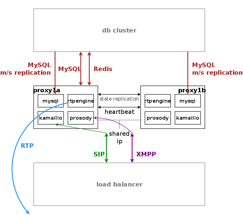
Proxy servers also come in pairs, and by default there are four pairs of proxies in a standard sip:carrier setup.
The proxies are responsible for doing the actual SIP routing and media handling and the XMPP presence and chat message deliveries. Each proxy pair can handle any subscriber on the overall system, compared to the concept of "home proxies" in other architectures. The advantage of this approach is that the overall system can be scaled extremely easily by adding more proxy pairs without having to redistribute subscribers.
Once a load balancer sends a new message to a proxy, the SIP transaction and/or dialog gets anchored to this proxy. That way it is ensured that a call starting on a proxy is also ended on the same proxy. Hence, the full range of feature handling like media relay, voicemail, fax, billing and rating is performed on this proxy. So, there is no a central point for various tasks, potentially leading to a non-scalable bottleneck. Due to the anchoring, proxies come in pairs and replicate all internal state information to the standby node via redis. In case of fail-over, the full signalling and media are moved to the standby node without interruption.
The complete static subscriber information like authentication credentials, number mappings, feature settings etc. are replicated from the db cluster down to the local MySQL instance of the proxies. The ratio of db read requests of static subscriber data versus reading and writing volatile and shared data is around 15:1, and this approach moves the majority of the static read operations from the central db cluster to the local proxy db.
Volatile and shared information needed by all proxies in the cluster is read from and written to the db cluster. This mainly includes SIP registration information and XMPP connection information.
Billing and rating is also performed locally on the proxies, and only completed CDRs (rated or unrated depending on whether rating is enabled) are transferred to the central db cluster for consumption via the northbound interfaces.
For SIP, the relevant instances on a proxy are kamailio acting as a stateful proxy for SIP registration and call routing, sems acting as a back-to-back user-agent for prepaid billing and application server, rtpengine as media relay and RTP/SRTP transcoder, and asterisk as voicemail server. XMPP is handled by an instance of prosody, and several billing processes mediate start and stop records into CDRs and rate them according to the relevant billing profiles.
If the sip:carrier is scaled beyond 250.000 subscribers and therefore exceeds one chassis, a second chassis is put into place. This chassis provides another two web servers, two db servers, two load balancers and 8 proxies, doubling the capacity of the system.
The DB cluster is the only node type which requires a notable change on the architecture. Once more than one db pair is deployed, the replication mechanism between db nodes changes from master/master between the nodes of the db1 pair to a synchronous multi-master replication over all db nodes on the system using Galera. This change makes it possible to scale both read and write requests over multiple nodes, while being transparent to all other nodes.
New proxy nodes replicate via master/slave from the first db node in the chassis as usual. Since the db cluster holds all provisioning information of all subscribers, the proxy nodes join the cluster transparently and will start serving subscribers as soon as all services on a new proxy are reachable from the load balancers.
Load balancers are completely stateless, so they start serving subscribers as soon as they are made visible to the subscribers. This could either be done via DNS round-robin, but the better approach is to configure a DNS SRV record, which allows for more fine-grained control like weighting load-balancer pairs and allowing fail-over from one pair to another on the client side.
The load balancers use the Path extension of SIP to make sure during SIP registration that calls targeted to a subscriber are routed via the same load balancer pair which the subscriber used during registration for proper traversal of symmetric NAT at the customer premise.
A SIP or XMPP request reaching a load balancer can be routed to any available proxy in the whole system, or only to proxies belonging to the same chassis as the load balancer, depending on the system configuration.
This architecture is not part of the standard deployment and is to be defined in the project plan! |
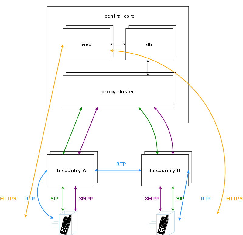
In case of a geographically distributed system spanning across multiple countries, different regulatory requirements have to be met for signalling and media, especially when it comes to if, where and how subscriber traffic can be intercepted. Countries might have the requirement to intercept traffic in the country, so the signalling and media must be anchored to an element in the country. Also if a media stream stays within a country, it is preferred to keep the media as close to the subscribers as possible to reduce latency, so relaying streams via a central core has to be avoided.
For this scenario, the sip:carrier makes it possible to move the load balancers directly into the countries. DNS settings for subscribers within the country ensure that they will always contact those load balancers, either using separate DNS settings per country for a SIP domain, or using GeoIP mechanisms in DNS to return the closest load balancer based on the location of the subscriber. To anchor media to the countries, the rtpengine instances are moved from the proxies to the load balancers and are controlled via the stateless kamailio instances on the load balancers instead of the kamailio instances on the proxies.
| | ||