| |
| |
Starting with version 2.7, the sip:carrier uses a dedicated network.yml file to configure the IP addresses of the system. The reason for this is to be able to access all IPs of all nodes for all services from any particular node in case of a distributed system on one hand, and in order to be able the generate /etc/network/interfaces automatically for all nodes based on this central configuration file.
The basic structure of the file looks like this:
hosts:
  self:
    role:
      - proxy
      - lb
      - mgmt
    interfaces:
      - eth0
      - lo
    eth0:
      ip: 192.168.51.213
      netmask: 255.255.255.0
      type:
        - sip_ext
        - rtp_ext
        - web_ext
        - web_int
    lo:
      ip: 127.0.0.1
      netmask: 255.255.255.0
      type:
        - sip_int
        - ha_int
Some more complete, sample configuration is shown in network.yml Overview Section B.3, “network.yml Overview” section of the handbook.
The file contains all configuration parameters under the main key: hosts
In sip:carrier systems all hosts of the system are defined, and the names are the actual host names instead of self, like this:
hosts:

  web01a:
    peer: web01b
    role: ...
    interfaces: ...

  web01b:
    peer: web01a
    role: ...
interfaces: ...There are three different main sections for a host in the config file, which are role, interfaces and the actual interface definitions.
role: The role setting is an array defining which logical roles a node will act as. Possible entries for this setting are:
lo, eth0, eth1 physical and a number of virtual interfaces,
like: bond0, vlanXXX
Addtional main parameters of a node:
hwaddr: MAC address of the interface
This must be filled in properly for the interface that is used as type
|
ip: IPv4 address of the node
v6ip: IPv6 address of the node; optional
netmask: IPv4 netmask
shared_ip: shared IPv4 address of the pair of nodes; this is a list of addresses
shared_v6ip: shared IPv6 address of the pair of nodes; optional; this is a
list of addresses
advertised_ip: the IP address that is used in SIP messages when the NGCP system
is behind NAT/SBC. An example of such a deployment is Amazon AMI, where the
server doesn’t have a public IP, so load-balancer component of NGCP needs to
know what his public domain is (→ advertised_ip).
type: type of services that the node provides; these are usually the VLANs
defined for a particular NGCP system.
You can assign a type only once per node. |
Available types are:
api_int: internal, API-based communication interface. It is used for the
internal communication of such services as faxserver, fraud detection and others.
aux_ext: interface for potentially insecure external components like remote
system log collection service.
For example the CloudPBX module can use it to provide time services and remote logging facilities to end customer devices. The type aux_ext is assigned to lo interface by default. If it is needed to expose this type to the public, it is recommended to assign the type aux_ext to a separate VLAN interface to be able to limit or even block the incoming traffic easily via firewalling in case of emergency, like a (D)DoS attack on external services. |
mon_ext: remote monitoring interface (e.g. SNMP)
rtp_ext: main (external) interface for media traffic
sip_ext: main (external) interface for SIP signalling traffic between NGCP
and other SIP endpoints
sip_ext_incoming: additional, optional interface for incoming SIP signalling
traffic
sip_int: internal SIP interface used by NGCP components (lb, proxy, etc.)
ssh_ext: command line (SSH) remote access interface
web_ext: interface for web-based or API-based provisioning and administration
web_int: interface for the administrator’s web panel, his API and generic
internal API communication
li_int: used for LI (Lawful Interception) traffic routing
ha_int: main communication interface between the nodes
boot_int: the default VLAN used to install nodes via PXE-boot method
rtp_int: internal interface for handling RTP traffic among NGCP nodes that
may reside in greater distance from each other, like in case of a specialised NGCP
configuration with centralized web / DB / proxy nodes and distributed LB nodes
(Please refer to Cluster Sets
Section 9.2.3, “Cluster Sets” section for further details)
Please note that, apart from the standard ones described so far, there might be other types defined for a particular NGCP system. |
vlan_raw_device: tells which physical interface is used by the particular VLAN
post_up: routes can be defined here (interface-based routing)
bond_XY: specific to "bond0" interface only; these contain Ethernet bonding properties
You have a typical deployment now and you are good to go, however you may need to do extra configuration depending on the devices you are using and functionality you want to achieve.
By default, the load-balancer listens on the UDP and TCP ports 5060 (kamailio→lb→port) and TLS port 5061 (kamailio→lb→tls→port). If you need to setup one or more extra SIP listening ports or IP addresses in addition to those standard ports, please edit the kamailio→lb→extra_sockets option in your /etc/ngcp-config/config.yml file.
The correct format consists of a label and value like this:
    extra_sockets:
      port_5064: udp:10.15.20.108:5064
      test: udp:10.15.20.108:6060
The label is shown in the outbound_socket peer preference (if you want to route calls to the specific peer out via specific socket); the value must contain a transport specification as in example above (udp, tcp or tls). After adding execute ngcpcfg apply:
ngcpcfg apply 'added extra socket' && ngcpcfg push all
The direction of communication through this SIP extra socket is incoming+outgoing. The sip:carrier will answer the incoming client registrations and other methods sent to the extra socket. For such incoming communication no configuration is needed. For the outgoing communication the new socket must be selected in the outbound_socket peer preference. For more details read the next section Section 9.2.2, “Extra SIP and RTP Sockets” that covers peer configuration for SIP and RTP in greater detail.
In this section you have just added an extra SIP socket. RTP traffic will still use your rtp_ext IP address. |
If you want to use an additional interface (with a different IP address) for SIP signalling and RTP traffic you need to add your new interface in the /etc/network/interfaces file. Also the interface must be declared in /etc/ngcp-config/network.yml.
Suppose we need to add a new SIP socket and a new RTP socket on VLAN 100. You can use the ngcp-network tool for adding interfaces without having to manually edit this file:
ngcp-network --set-interface=eth0.100 --host=slb01a --ip=auto --netmask=auto --type=sip_ext_incoming
ngcp-network --set-interface=eth0.100 --host=slb01b --ip=auto --netmask=auto --type=sip_ext_incoming
ngcp-network --set-interface=eth0.100 --host=prx01a --ip=auto --netmask=auto --type=rtp_int_100
ngcp-network --set-interface=eth0.100 --host=prx01b --ip=auto --netmask=auto --type=rtp_int_100
The generated file should look like the following:
slb01a:
..
..
    eth0.100:
      hwaddr: ff:ff:ff:ff:ff:ff
      ip: 192.168.1.2
      netmask: 255.255.255.0
      shared_ip:
        - 192.168.1.3
      shared_v6ip: ~
      type:
        - sip_ext_incoming
..
..
    interfaces:
      - lo
      - eth0
      - eth0.100
      - eth1
..
..
prx01a:
..
..
    eth0.100:
      hwaddr: ff:ff:ff:ff:ff:ff
      ip: 192.168.1.20
      netmask: 255.255.255.0
      shared_ip:
        - 192.168.1.30
      shared_v6ip: ~
      type:
        - rtp_int_100
..
..
    interfaces:
      - lo
      - eth0
      - eth0.100
      - eth1
..
..
slb01b:
..
..
    eth0.100:
      hwaddr: ff:ff:ff:ff:ff:ff
      ip: 192.168.1.4
      netmask: 255.255.255.0
      shared_ip:
        - 192.168.1.3
      shared_v6ip: ~
      type:
        - sip_ext_incoming
..
..
    interfaces:
      - lo
      - eth0
      - eth0.100
      - eth1
..
..
prx01b:
..
..
    eth0.100:
      hwaddr: ff:ff:ff:ff:ff:ff
      ip: 192.168.1.40
      netmask: 255.255.255.0
      shared_ip:
        - 192.168.1.30
      shared_v6ip: ~
      type:
        - rtp_int_100
..
..
    interfaces:
      - lo
      - eth0
      - eth0.100
      - eth1
As you can see from the above example, extra SIP interfaces must have type sip_ext_incoming. While sip_ext should be listed only once per host, there can be multiple sip_ext_incoming interfaces. The direction of communication through this SIP interface is incoming only. The sip:carrier will answer the incoming client registrations and other methods sent to this address and remember the interfaces used for clients' registrations to be able to send incoming calls to him from the same interface.
In order to use the interface for the outbound SIP communication it is necessary to add it to extra_sockets section in /etc/ngcp-config/config.yml and select in the outbound_socket peer preference.
So if using the above example we want to use the vlan100 IP as source interface towards a peer, the corresponding section may look like the following:
    extra_sockets:
      port_5064: udp:10.15.20.108:5064
      test: udp:10.15.20.108:6060
      int_100: udp:192.168.1.3:5060
The changes have to be applied:
ngcpcfg apply 'added extra SIP and RTP socket' && ngcpcfg push all
After applying the changes, a new SIP socket will listen on IP 192.168.1.3 on slb01 node and this socket can now be used as source socket to send SIP messages to your peer for example. In above example we used label int_100. So the new label "int_100" is now shown in the outbound_socket peer preference.
Also, RTP socket is now listening on 192.168.1.30 on prx01 node and you can choose the new RTP socket to use by setting parameter rtp_interface to the Label "int_100" in your Domain/Subscriber/Peer preferences.
In a sip:carrier system it is possible to have geographically distributed nodes in the same logical NGCP unit. Such a configuration typcally involves the following elements:
In case of such an NGCP node configuration it is possible to define cluster sets which are collections of NGCP nodes providing the load balancer functionality.
Cluster sets can be assigned to subscriber domains or SIP peers and will determine the route of SIP and RTP traffic for those sets of SIP endpoints:
There are 2 places in NGCP’s main configuration files where an entry for cluster sets must be inserted:
Declaration of cluster sets
This happens in /etc/ngcp-config/config.yml file, see an example below:
cluster_sets:
  default:
    dispatcher_id: 50
  default_set: default
  poland:
    dispatcher_id: 51
  type: distributed
Configuration entries are:
default and poland; the cluster set default is always defined, even
if cluster sets are not used
central or distributed
Assignment of cluster sets
This happens in /etc/ngcp-config/network.yml file, see an example below:
  .
  .
  lb03a:
    .
    .
    vlan792:
      cluster_sets:
        - poland
      hwaddr: 00:00:00:00:00:00
      ip: 172.30.61.37
      netmask: 255.255.255.240
      shared_ip: 172.30.61.36
      type:
        - sip_int
      vlan_raw_device: bond0
In the network configuration file typically the load balancer (lb) nodes are
assigned to cluster sets. More precisely: network interfaces of load balancer nodes
that have sip_int type — that are used for SIP signalling and NGCP’s internal
rtpengine command protocol — are assigned to cluster sets.
In order to do such an assignment a cluster set’s label has to be added to the
cluster_sets parameter, which is a list.
After modifying network configuration with cluster sets, the new configuration must be applied in the usual way:
> ngcpcfg apply 'Added cluster sets'
> ngcpcfg push all
For both SIP peers and subscriber domains you can select the cluster set labels
predefined in config.yml file.
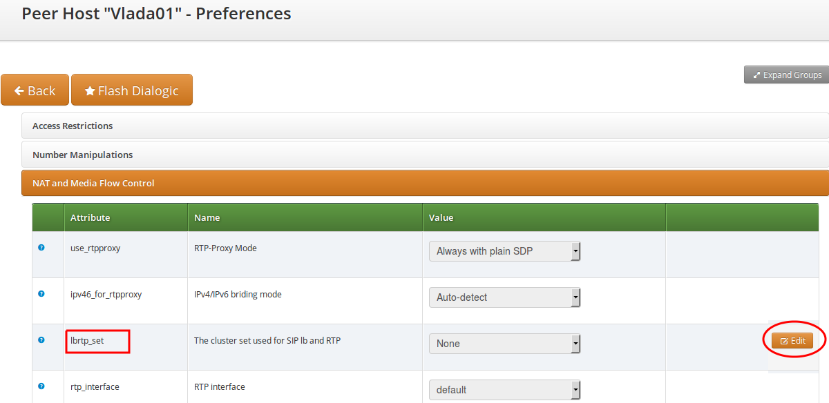
SIP peers: In order to select a particular cluster set for a SIP peer you have
to navigate to Peerings → select the peering group → select the peering server
→ Preferences → NAT and Media Flow Control and then Edit lbrtp_set parameter.
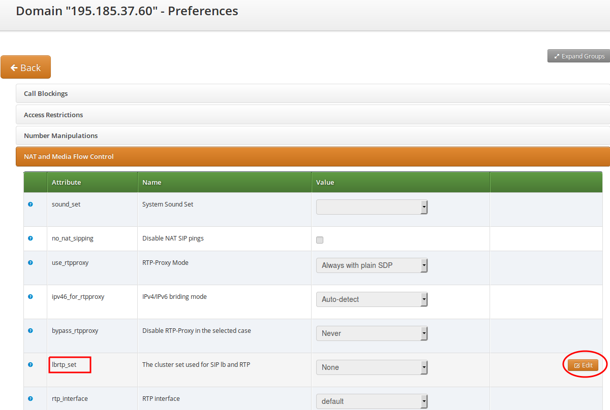
Domains: In order to select a particular cluster set for a domain you have
to navigate to Domains → select the domain → Preferences → NAT and Media Flow
Control and then Edit lbrtp_set parameter.
| | ||