| |
| |
The following chapter will provide the step by step instructions on how to put the sip:provider PRO into operations.
The sip:provider PRO ships fully pre-installed on two servers. The hardware dimensions and weight is defined in the following figure:
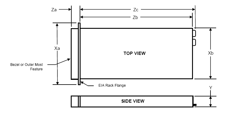
Xa | Xb (Width) | Y (Height) | Za w/ bezel | Za w/o bezel | Zb (Depth) | Zc |
482.4mm | 434mm | 42.4mm | 35mm | 21mm | 612.6mm | 641.9mm |
Weight: 15kg
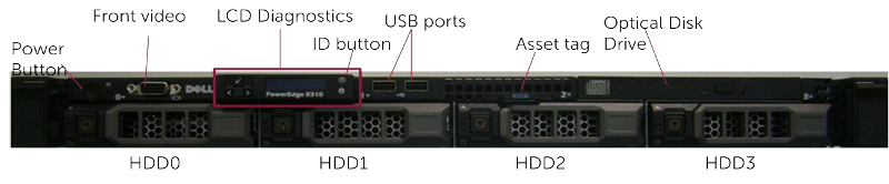
The redundant PSUs include LEDs which indicate the status of the PSU:
In order to put the sip:provider PRO into operations, you need to rack-mount it into 19" racks.
What you will find in the box is the following equipment:
What you will additionally need and what is not part of the shipment is the following parts:
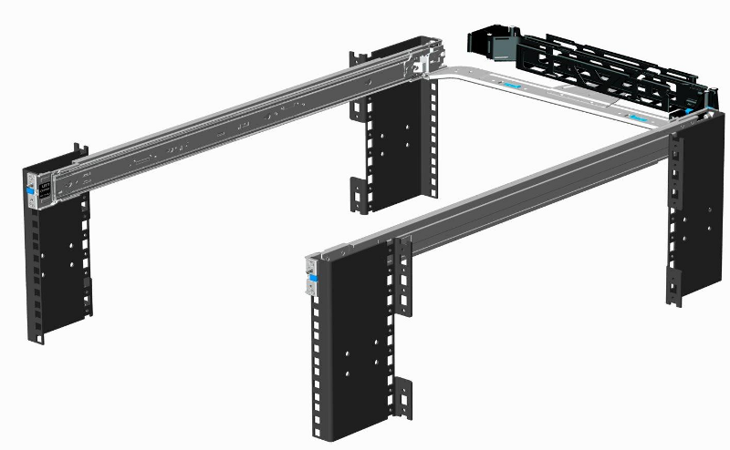
Install the two servers into the rack (either into a single one or into two geographically distributed ones). The rails shipped with the servers should fit into standard 4-Post 19" racks. If it does not fit, please consult your rack vendor to get proper rails.
The following figure shows the mounted rails. Please note that the cable management arm on the top right is NOT included.
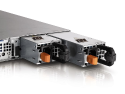
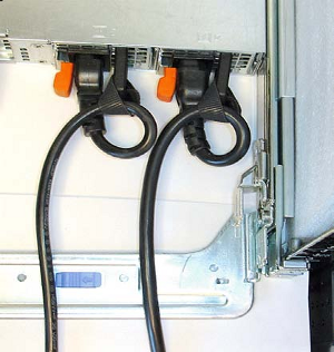
Each server has two redundant Power Supply Units (PSU). Connect one PSU to your normal power circuit and the other one to an Uninterruptible Power Supply Unit (UPS) to gain the maximum protection against power failures.
The cabling should look like in the following picture to prevent accidental power cuts:
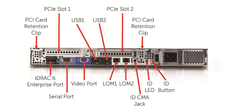
For each of the two servers, connect a straight CAT5 cable to the first network interface and hook it up to the corresponding access switch port.
Then patch a cross-link with another straight CAT5 cable between the two servers by connecting the cable to the second network interface. The direct cross cable is used for maximum availability, because this connection is used by the servers to communicate with each other internally. Only use a switch in between if there is no other way to connect the two ports (e.g. if it’s geographically distributed).
In case you are using a switch for cross-link make sure to enable portfast mode on Cisco switches. The thing is that STP puts the port into learning mode for 90 seconds after it comes up for the first time. During this learning phase, the link is technically up, but no traffic passes through, so heartbeat will detect other node as dead during boot. Portfast tells the switch to skip the learning phase and go to forwarding state right away: spanning-tree portfast [trunk].
| | ||