| |
| |
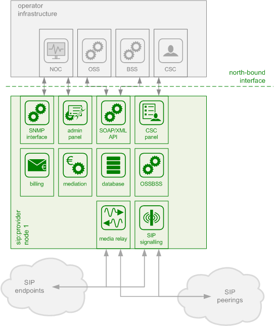
The sip:provider CE platform is one single node running all necessary components of the system. The components are outlined in the following figure:
The main building blocks of the sip:provider CE are:
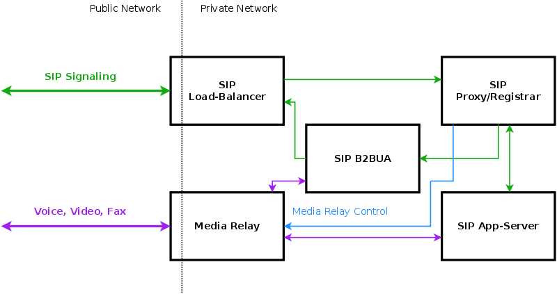
In SIP-based communication networks, it is important to understand that the signaling path (e.g. for call setup and tear-down) is completely independent of the media path. On the signaling path, the involved endpoints negotiate the call routing (which user calls which endpoint, and via which path - e.g. using SIP peerings or going through the PSTN - the call is established) as well as the media attributes (via which IPs/ports are media streams sent and which capabilities do these streams have - e.g. video using H.261 or Fax using T.38 or plain voice using G.711). Once the negotiation on signaling level is done, the endpoints start to send their media streams via the negotiated paths.
The components involved in SIP and Media on the sip:provider CE are shown in the following figure:
The SIP load-balancer is a Kamailio instance acting as ingress and egress point for all SIP traffic to and from the system. It’s a high-performance SIP proxy instance based on Kamailio and is responsible for sanity checks of inbound SIP traffic. It filters broken SIP messages, rejects loops and relay attempts and detects denial-of-service and brute-force attacks and gracefully handles them to protect the underlying SIP elements. It also performs the conversion of TLS to internal UDP and vice versa for secure signaling between endpoints and the sip:provider CE, and does far-end NAT traversal in order to enable signaling through NAT devices.
The load-balancer is the only SIP element in the system which exposes a SIP interface to the public network. Its second leg binds in the switch-internal network to pass traffic from the public internet to the corresponding internal components.
The name load-balancer comes from the fact that in the commercial version, when scaling out the system beyond just one pair of servers, the load-balancer instance becomes its own physical node and then handles multiple pairs of proxies behind it.
On the public interface, the load-balancer listens on port 5060 for UDP and TCP, as well as on 5061 for TLS connections. On the internal interface, it speaks SIP via UDP on port 5060 to the other system components, and listens for XMLRPC connections on TCP port 5060, which is used by the OSSBSS system to control the daemon.
Its config files reside in /etc/ngcp-config/templates/etc/kamailio/lb/, and changes to these files are applied by executing ngcpcfg apply.
The SIP load-balancer can be managed via the commands |
The SIP proxy/registrar (or short proxy) is the work-horse of the sip:provider CE. It’s also a separate Kamailio instance running in the switch-internal network and is connected to the provisioning database via MySQL, authenticates the endpoints, handles their registrations on the system and does the call routing based on the provisioning data. For each call, the proxy looks up the provisioned features of both the calling and the called party (either subscriber or domain features if it’s a local caller and/or callee, or peering features if it’s from/to an external endpoint) and acts accordingly, e.g. by checking if the call is blocked, by placing call-forwards if applicable and by normalizing numbers into the appropriate format, depending on the source and destination of a call.
It also writes start- and stop-records for each call, which are then transformed into call detail records (CDR) by the mediation system.
If the endpoints indicate negotiation of one or more media streams, the proxy also interacts with the Media Relay to open, change and close port pairs for relaying media streams over the sip:provider CE, which is especially important to traverse NAT.
The proxy listens on UDP port 5062 in the system-internal network. It cannot be reached directly from the outside, but only via the SIP load-balancer.
Its config files reside in /etc/ngcp-config/templates/etc/kamailio/proxy/, and changes to these files are applied by executing ngcpcfg apply.
The SIP proxy can be controlled via the commands |
The SIP B2BUA (also called SBC within the system) decouples the first call-leg (calling party to sip:provider CE) from the second call-leg (sip:provider CE to the called party).
The software part used for this element is SEMS.
This element is typically optional in SIP systems, but it is always used for SIP calls (INVITE) that don’t have the sip:provider CE as endpoint. It acts as application server for various scenarios (e.g. for feature provisioning via Vertical Service Codes and as Conferencing Server) and performs the B2BUA decoupling, topology hiding, caller information hiding, SIP header and Media feature filtering, outbound registration, outbound authentication and call length limitation as well as Session Keep-Alive handler.
Due to the fact that typical SIP proxies (like the load-balancer and proxy in the sip:provider CE) do only interfere with the content of SIP messages where it’s necessary for the SIP routing, but otherwise leave the message intact as received from the endpoints, whereas the B2BUA creates a new call leg with a new SIP message from scratch towards the called party, SIP message sizes are reduced significantly by the B2BUA. This helps to bring the message size under 1500 bytes (which is a typical default value for the MTU size) when it leaves the sip:provider CE. That way, chances of packet fragmentation are quite low, which reduces the risk of running into issues with low-cost SOHO routers at customer sides, which typically have problems with UDP packet fragmentation.
The SIP B2BUA only binds to the system-internal network and listens on UDP port 5080 for SIP messages from the load-balancer or the proxy, on UDP port 5040 for control messages from the cli tool and on TCP port 8090 for XMLRPC connections from the OSSBSS to control the daemon.
Its configuration files reside in /etc/ngcp-config/templates/etc/ngcp-sems, and changes to these files are applied by executing ngcpcfg apply.
The SIP B2BUA can be controlled via the commands |
The SIP App-Server is an Asterisk instance used for voice applications like Voicemail and Reminder Calls. Asterisk uses the MySQL database as a message spool for voicemail, so it doesn’t directly access the file system for user data. The voicemail plugin is a slightly patched version based on Asterisk 1.4 to make Asterisk aware of the sip:provider CE internal UUIDs for each subscriber. That way a SIP subscriber can have multiple E164 phone numbers, but all of them terminate in the same voicebox.
The App-Server listens on the internal interface on UDP port 5070 for SIP messages and by default uses media ports in the range from UDP port 10000 to 20000.
The configuration files reside in /etc/ngcp-config/templates/etc/asterisk, and changes to these files are applied by executing ngcpcfg apply.
The SIP App-Server can be controlled via the commands |
The Media Relay (also called rtpengine) is a Kernel-based packet relay, which is controlled by the SIP proxy. For each media stream (e.g. a voice and/or video stream), it maintains a pair of ports in the range of port number 30000 to 40000. When the media streams are negotiated, rtpengine opens the ports in user-space and starts relaying the packets to the addresses announced by the endpoints. If packets arrive from different source addresses than announced in the SDP body of the SIP message (e.g. in case of NAT), the source address is implicitly changed to the address the packets are received from. Once the call is established and the rtpengine has received media packets from both endpoints for this call, the media stream is pushed into the kernel and is then handled by a custom Sipwise iptables module to increase the throughput of the system and to reduce the latency of media packets.
The rtpengine internally listens on UDP port 12222 for control messages from the SIP proxy. For each media stream, it opens two pairs of UDP ports on the public interface in the range of 30000 and 40000 per default, one pair on odd port numbers for the media data, and one pair on the next even port numbers for meta data, e.g. RTCP in case of RTP streams. Each endpoint communicates with one dedicated port per media stream (opposed to some implementations which use one pair for both endpoints) to avoid issues in determining where to send a packet to. The rtpengine also sets the QoS/ToS/DSCP field of each IP packet it sends to a configured value, 184 (0xB8, expedited forwarding) by default.
The kernel-internal part of the rtpengine is facilitated through an iptables module having the target name RTPENGINE. If any additional firewall or packet filtering rules are installed, it is imperative that this rule remains untouched and stays in place. Otherwise, if the rule is removed from iptables, the kernel will not be able to forward the media packets and forwarding will fall back to the user-space daemon. The packets will still be forwarded normally, but performance will be much worse under those circumstances, which will be especially noticeable when a lot of media streams are active concurrently. See the section on Firewalling for more information.
The rtpengine configuration file is /etc/ngcp-config/templates/etc/default/ngcp-rtpengine-daemon, and changes to this file are applied by executing ngcpcfg apply. The UDP port range can be configured via the config.yml file under the section rtpproxy. The QoS/ToS value can be changed via the key qos.tos_rtp.
The Media Relay can be controlled via the commands |
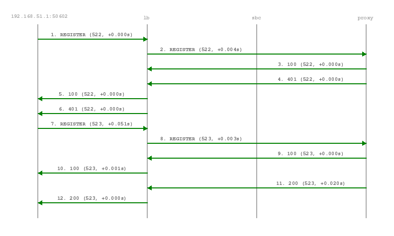
The subscriber endpoint starts sending a REGISTER request, which gets challenged by a 401. After calculating the response of the authentication challenge, it sends the REGISTER again, including the authentication response. The SIP proxy looks up the credentials of the subscriber in the database, does the same calculation, and if the result matches the one from the subscriber, the registration is granted.
The SIP proxy writes the content of the Contact header (e.g. sip:me@1.2.3.4:1234;transport=UDP) into its location table (in case of NAT the content is changed by the SIP load-balancer to the IP/port from where the request was received), so it knows where the reach a subscriber in case on an inbound call to this subscriber (e.g. sip:someuser@example.org is mapped to sip:me@1.2.3.4:1234;transport=UDP and sent out to this address).
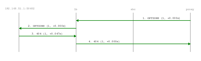
If NAT is detected, the SIP proxy sends a OPTION message to the registered contact every 30 seconds, in order to keep the NAT binding on the NAT device open. Otherwise, for subsequent calls to this contact, the sip:provider PRO wouldn’t be able to reach the endpoint behind NAT (NAT devices usually drop a UDP binding after not receiving any traffic for ~30-60 seconds).
By default, a subscriber can register 5 contacts for an Address of Record (AoR, e.g. sip:someuser@example.org).
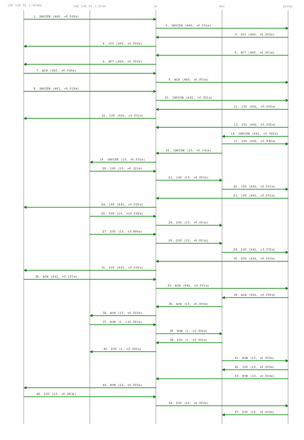
The calling party sends an INVITE (e.g. sip:someuser@example.org) via the SIP load-balancer to the SIP proxy. The proxy replies with an authorization challenge in the 407 response, and the calling party sends the INVITE again with authentication credentials. The SIP proxy checks if the called party is a local user. If it is, and if there is a registered contact found for this user, then (after various feature-related tasks for both the caller and the callee) the Request-URI is replaced by the URI of the registered contact (e.g. sip:me@1.2.3.4:1234;transport=UDP). If it’s not a local user but a numeric user, a proper PSTN gateway is being selected by the SIP proxy, and the Request-URI is rewritten accordingly (e.g. sip:+43123456789@2.3.4.5:5060).
Once the proxy has finished working through the call features of both parties involved and has selected the final destination for the call, and - optionally - has invoked the Media Relay for this call, the INVITE is sent to the SIP B2BUA. The B2BUA creates a new INVITE message from scratch (using a new Call-ID and a new From-Tag), copies only various and explicitly allowed SIP headers from the old message to the new one, filters out unwanted media capabilities from the SDP body (e.g. to force audio calls to use G.711 as a codec) and then sends the new message via the SIP load-balancer to the called party.
SIP replies from the called party are passed through the elements back to the calling party (replacing various fields on the B2BUA to match the first call leg again). If a reply with an SDP body is received by the SIP proxy (e.g. a 183 or a 200), the Media Relay is invoked again to prepare the ports for the media stream.
Once the 200 is routed from the called party to the calling party, the media stream is fully negotiated, and the endpoints can start sending traffic to each outer (either end-to-end or via the Media Relay). Upon reception of the 200, the SIP proxy writes a start record for the accounting process. The 200 is also acknowledged with an ACK message from the calling party to the called party, according to the SIP 3-way handshake.
Either of the parties can tear down the media session at any time by sending a BYE, which is passed through to the other party. Once the BYE reaches the SIP proxy, it instructs the Media Relay to close the media ports, and it writes a stop record for accounting purposes. Both the start- and the stop-records are picked up by the mediator service in a regular interval and are converted into a Call Detail Record (CDR), which will be rated by the rate-o-mat process and can be billed to the calling party.
The SIP B2BUA acts as refresher for the Session-Timer mechanism as defined in RFC 4028. If the endpoints indicate support for the UPDATE method during call-setup, then the SIP B2BUA will use an UPDATE message if enabled per peer, domain or subscriber via Provisioning to check if the endpoints are still alive and responsive. Both endpoints can renegotiate the timer within a configurable range. All values can be tuned using the Admin Panel or the APIs using Peer-, Domain- and Subscriber-Preferences.
Keep in mind that the values being used in the signaling are always half the value being configured. So if you want to send a keep-alive every 300 seconds, you need to provision sst_expires to 600. |
If one of the endpoints doesn’t respond to the keep-alive messages or answers with 481 Call/Transaction Does Not Exist, then the call is torn down on both sides. This mechanism prevents excessive over-billing of calls if one of the endpoints is not reachable anymore or "forgets" about the call. The BYE message sent by the B2BUA triggers a stop-record for accounting and also closes the media ports on the Media Relay to stop the call.
Beside the Session-Timer mechanism to prevent calls from being lost or kept open, there is a maximum call length of 21600 seconds per default defined in the B2BUA. This is a security/anti-fraud mechanism to prevent overly long calls causing excessive costs.
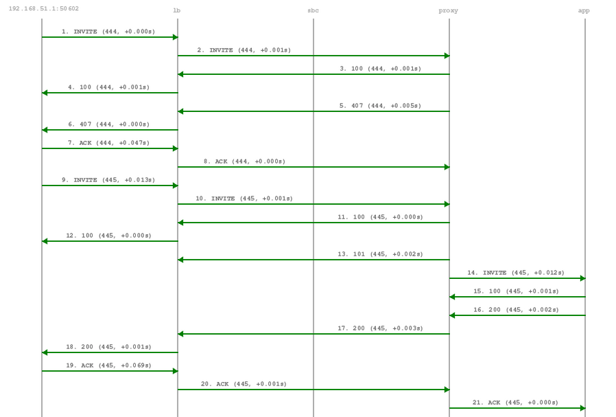
Calls to the Voicebox (both for callers leaving a voicemail message and for voicebox owners managing it via the IVR menu) are passed directly from the SIP proxy to the App-Server without a B2BUA. The App-Server maintains its own timers, so there is no risk of over-billing or overly long calls.
In such a case where an endpoint talks via the Media Relay to a system-internal endpoint, the Media Relay bridges the media streams between the public in the system-internal network.
In case of an endpoint leaving a new message on the voicebox, the Message-Waiting-Indication (MWI) mechanism triggers the sending of a unsolicited NOTIFY message, passing the number of new messages in the body. As soon as the voicebox owner dials into his voicebox (e.g. by calling sip:voicebox@example.org from his SIP account), another NOTIFY message is sent to his devices, resetting the number of new messages.
The sip:provider CE does not require your device to subscribe to the MWI service by sending a SUBSCRIBE (it would rather reject it). On the other hand, the endpoints need to accept unsolicited NOTIFY messages (that is, a NOTIFY without a valid subscription), otherwise the MWI service will not work with these endpoints. |
| | ||