This chapter will provide the step by step instructions on how to put Sipwise C5 into operations.
Sipwise provides Sipwise C5 platform fully pre-installed on two Dell PowerEdge R330 servers. Their most important characteristics are:
- Up to 8 pcs. of 2.5" storage drives (HDD or SSD); shipped with 4 drives installed and configured as RAID10 array
- Gbit Ethernet ports: 2 on-board and 2 additional ports (optional)
- iDRAC module for remote maintenance
| info | |
Please be aware that prior to Q3 2016 Sipwise used to provide its Sipwise C5 platform on older Dell PowerEdge server models: R310 and R320. |
The hardware dimensions are defined in the following figure:
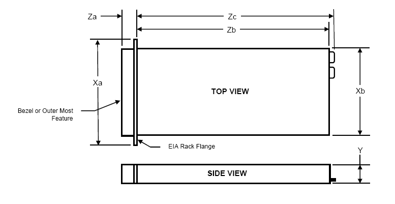
Xa | Xb (Width) | Y (Height) | Za w/ bezel | Za w/o bezel | Zb (Depth) | Zc |
482.4mm | 434mm | 42.8mm | 35mm | 21mm | 610mm | 639.5mm |
Weight of the server with storage drives and internal components installed: 13.4kg
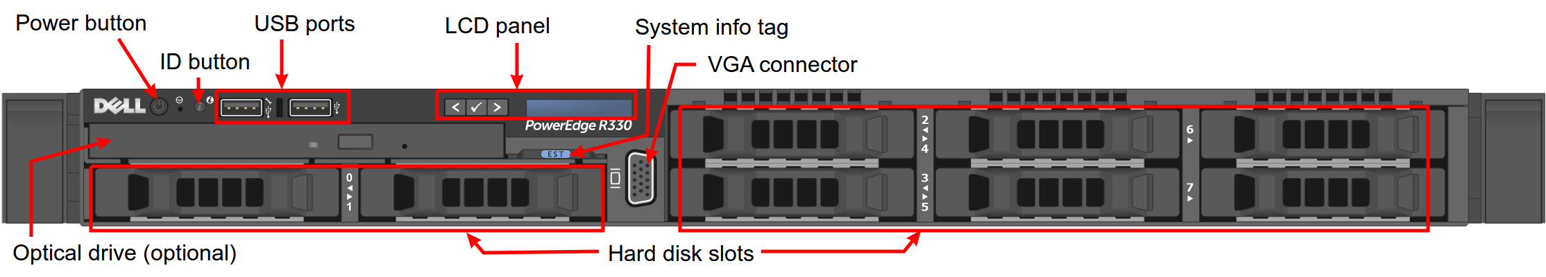
The front view of a current Sipwise C5 Dell R330 server:
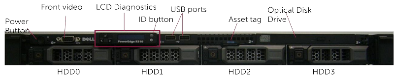
The front view of a former Sipwise C5 Dell R310…:
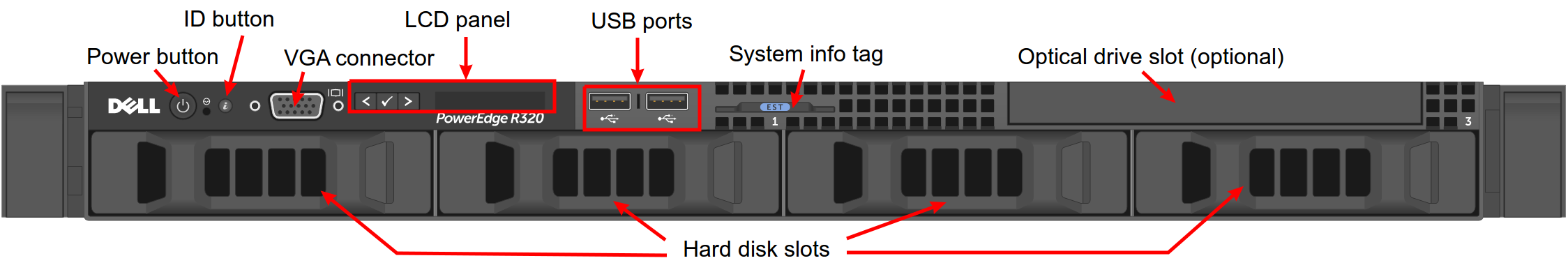
…and Dell R320 server:
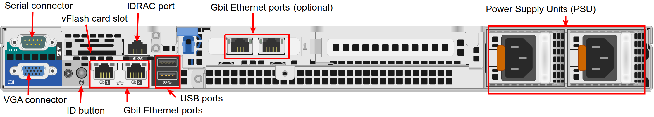
The rear view of a current Sipwise C5 Dell R330 server:
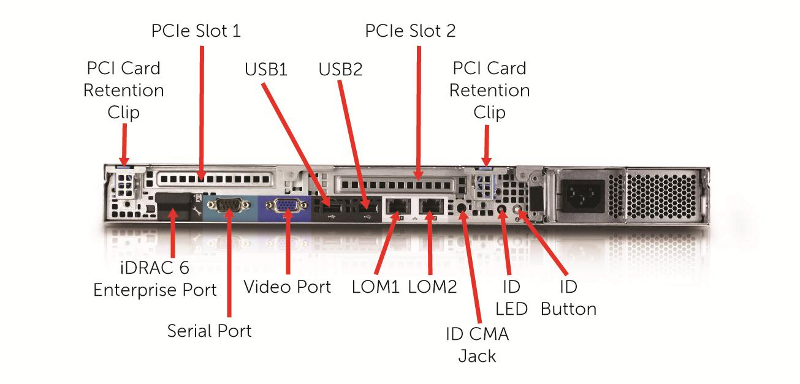
The rear view of a former Sipwise C5 Dell R310…:
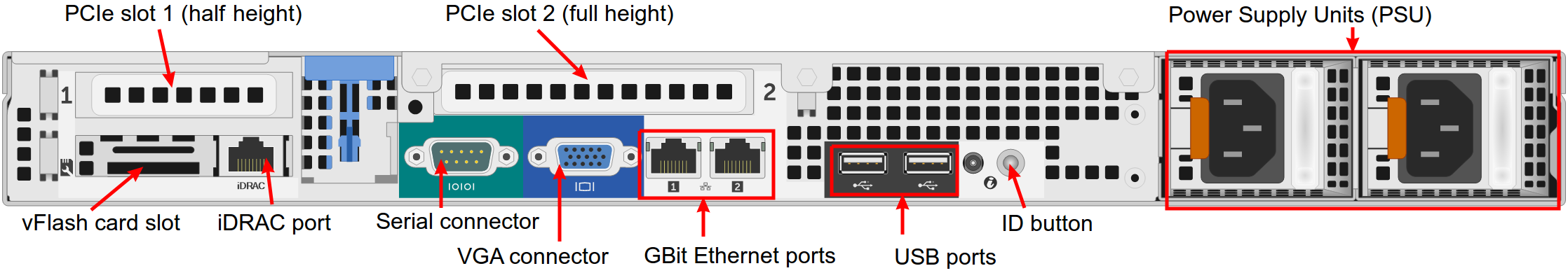
…and Dell R320 server:
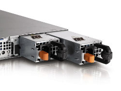
The servers are equipped with 2 redundant, hot-swappable PSUs, which are accessible from the rear side and located on the right of the chassis:
The redundant PSUs include LEDs that indicate the status of the PSU:
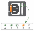
- The indicator is solidly lit green: A valid power source is connected to the PSU and the PSU is operational.
The indicator is flashing green: The PSU firmware is being updated.
caution Do not disconnect the power cord or unplug the PSU when updating the firmware. If a firmware update is interrupted, the PSUs will not function. You must roll back the PSU firmware by using Dell Lifecycle Controller. For more information, see Dell Lifecycle Controller User’s Guide at Dell.com/idracmanuals.
- The indicator is flashing green and turns off: When hot-adding a PSU, the PSU handle flashes green five times at 4 Hz rate and turns off. This indicates that there is a PSU mismatch with respect to efficiency, feature set, health status, and supported voltage. Ensure that both the PSUs are the same.
The indicator is flashing amber: Indicates a problem with the PSU.
caution When correcting a PSU mismatch, replace only the PSU with the flashing indicator. Swapping the other PSU to make a matched pair can result in an error condition and unexpected system shutdown. To change from a High Output configuration to a Low Output configuration or vice versa, you must turn off the system.
caution AC PSUs support both 220 V and 110 V input voltages with the exception of Titanium PSUs, which support only 220 V. When two identical PSUs receive different input voltages, they can output different wattages, and trigger a mismatch.
caution If two PSUs are used, they must be of the same type and have the same maximum output power.
caution Combining AC and DC PSUs is not supported and triggers a mismatch.
- The indicator is not lit: Power is not connected.
In order to put Sipwise C5 into operations, you need to rack-mount it into 19" racks.
You will find the following equipment in the box:
- 2 servers
- 2 pairs of rails to rack-mount the servers
- 2 cable management arms
You will additionally need the following parts as they are not part of the distribution:
4 power cables
info The exact type required depends on the location of installation, e.g. there are various forms of power outlets in different countries.
- At least 2 CAT5 cables to connect the servers to the access switches for external communication
- 1 CAT5 cable to directly connect the two servers for internal communication
Install the two servers into the rack (either into a single one or into two geographically distributed ones).
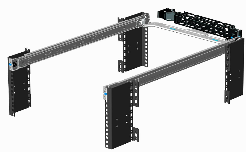
The rails shipped with the servers fit into standard 4-Post 19" racks. If they do not fit, please consult your rack vendor to get proper rails.
The following figure shows the mounted rails:
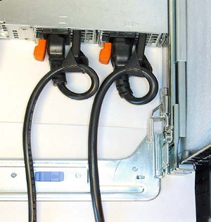
Each server has two redundant Power Supply Units (PSU). Connect one PSU to your normal power circuit and the other one to an Uninterruptible Power Supply Unit (UPS) to gain the maximum protection against power failures.
The cabling should look like in the following picture to prevent accidental power cuts:
- Internal Communication
- The high availability (HA) feature of Sipwise C5 requires that a direct Ethernet connection between the servers is established. One of the network interfaces must be dedicated to this functionality.
- External Communication
- Remaining network interfaces may be used to make the servers publicly available for communication services (SIP, messaging, etc.) and also for their management and maintenance.
Patch a cross-link with a straight CAT5 cable between the two servers by connecting the cable to the network interface assigned to the HA component by Sipwise. The direct cross cable is applied for maximum availability because this connection is used by the servers to communicate with each other internally.
| important | |
We strongly suggest against using a switch in between the servers for this internal interface. Using a switch is acceptable only if there is no another way to connect the two ports (e.g. if you configure a geographically distributed installation). |
| info | |
In case you are using a switch for cross-link make sure to enable portfast
mode on Cisco switches. The thing is that STP puts the port into learning mode for
90 seconds, after it comes up for the first time. During this learning phase, the
link is technically up, but no traffic passes through, so |
For both servers, depending on the network configuration, connect one or more straight CAT5 cables to the ports on the servers network cards and plug them into the corresponding switch ports. Information about proper ports of the servers to be used for this purpose are provided by Sipwise.